


 |
Lynton and Barnstaple Railway Signalling at Pilton |
|
||||||||
|
||||||||||
This page describes the signalling at Pilton on the former narrow-gauge Lynton & Barnstaple Railway (L&BR). Please see the separate Introduction to L&BR Signalling page for general background information and details of other pages on RailWest about the signalling of the L&BR. Click here for more general historical details about the L&BR and a Bibliography.
Pilton was the location of the L&BR's locomotive and carriage works on the outskirts of Barnstaple, about a quarter of a mile from Barnstaple Town station, and there was also a small goods yard there. A signal-box and passing-loop were provided here and these form the subject of this page. The location appears to have been described variously as Pilton, Pilton Bridge, Pilton Yard and even Pilton Road in different railway records, but for simplicity the term 'Pilton' is used in RailWest except when a particular variant is necessary for historical accuracy. There are separate pages on RailWest about the other passing-loops at the main intermediate stations on the line, and also about the actual L&BR signals and signal-boxes themselves.
 |
|
|||||||||||||
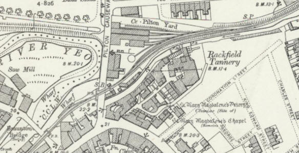
| <<< A map of Pilton Yard surveyed in 1903 | ||||||||||||||
The signalling at Pilton was installed by Evans O'Donnell (EoD), who were the L&BR's original signalling contractor, although after 1922 some alterations or replacements were done by the Southern Railway (SR) using equipment of former London and South Western Railway (L&SWR) design. The basic layout at Pilton (click here to see a larger map) consisted of a passing-loop on the single-line between Barnstaple Town and Chelfham stations, laid on a long reverse curve running roughly south-west to north-east in the form of an elongated 'S'. On the Down (north-west) side of the Down Loop there was an additional loop - not used by passenger trains - from which various sidings trailed into the works and goods yard. The signal-box (marked 'S.B' on the map above) was located on the Down side of the line at the Barnstaple Town end of the loop.
Immediately south-west of the passing-loop the single-line crossed Pilton Causeway by a gated level-crossing and then about 100 yards further on towards Barnstaple Town station there was another gated level-crossing across Braunton Road. These crossings were 29 chains and 20 chains respectively from Barnstaple Town station and there was an 8 MPH speed restriction over both crossings in both directions. Between these two crossings on the Down side of the line was Pilton Quay siding, which served a wharf on the River Yeo. In the early years this siding was accessed by a point at the Pilton end facing to Up trains, but at an unknown later date (believed to have been pre-1923) that connection was removed and replaced by a point at the Town end facing to Down trains.
Known features of the original signalling at Pilton in 1898
Note: the signal and point letters shown on the diagrams on this page are purely arbitrary and have been included merely for identification purposes within RailWest; pairs of points given the same letter are assumed to have been worked from the same lever.
On 4-May-1898 Lt Col HA Yorke inspected the L&BR on behalf of the Board of Trade (BoT) and his subsequent Inspection Report contains some brief details about the signalling at Pilton, but unfortunately no numbered signal-diagram for Pilton has come to light yet so a number of unanswered questions remain about some features. The outline diagram above is intended to show those features of the signalling which are known to have existed at Pilton at the time of the opening of the railway in 1898. The installation included two ground-frames (GF), one at the north end of the Yard and the other at the Quay Siding.
It is curious that the facing point for the Up Loop (marked 'A') was situated further away from the signal-box than the maximum distance permitted at that time by the BoT for mechanical operation, yet Col Yorke made no mention of this discrepancy in his Inspection Report. It will be noted that, in common with the initial arrangements at the other intermediate passing-loops, there were no Starting signals at the end of either loop and none were ever provided here (but see the section on Signals below for more about the Up Starting (US)).
One unsolved mystery about the original signalling arises from a photograph taken at Pilton yard on or about the opening day in 1898, which shows two signal wires extending alongside the Up Loop towards the Lynton end. Presumably one of these wires was for the Up Home signal (UH), but the purpose of the other wire is unknown, as there was no other known signal at the Lynton end of the loop. One possible explanation might be that Pilton initially had been equipped with an Up Distant signal (presumably because the Up Home could not be sighted from a sufficient distance), but there is no other supporting evidence for that theory as no such signal is mentioned in any surviving records from that period.
Gate Bolts. It is presumed, on the basis of available evidence and contemporary practice, that at both level-crossings the gates were bolted across the road by a 'gate bolt' lever in the lever-frame in the signal-box. It is not known for certain whether those levers bolted the gates across the road when the levers were in their 'normal' or their 'reverse' position, as both methods were used by different railway companies and signalling contractors. However in the light of comments at the Inquest into the fatal accident at Braunton Road crossing on 1-January-1910 (as reported by the North Devon Journal [1]), where the signalman is reported as saying that he had pulled his lever to lock the gates, then it is believed that the gate-bolts were effective when their levers were reversed. It is not known for certain also whether there was a separate bolt lever for each crossing or a single lever for both crossings, but the former is presumed as being 'usual practice'. There might have been occasional requirements to shunt out of the loop at the Barnstaple Town end, but without proceeding as far as Braunton Road crossing (eg in order to access the Quay siding in its original arrangement), which would have necessitated the gates at Braunton Road being closed unnecessarily if there was only one bolt lever.
Arm Repeaters. The National Archives file MT6/876/8 includes a report for the BoT compiled by W Gamble (apparently an employee of the railway company) providing information in advance of the BoT Inspection on matters such as the location of all the signals etc. This report includes a (proposed) requirement for the Up Home and Down Home signals to be 'repeated' - in other words, to have electrical indicators installed in the signal-box to show whether the signal arms were 'on' or 'off'. It is not known if such indicators were actually provided at Pilton nor, if so, of what pattern.
|
Pilton signal-box (SB) was located on the down side of the line between Pilton Causeway crossing and the Town end of the passing-loop. It was an elevated structure to an EoD design, but unlike the all-timber SB at Barnstaple Town it originally had a timber upper-floor superstructure on a tall masonry lower floor. However at some unknown date (possibly circa-1918) the building was reduced substantially in height, with the lower floor becoming in effect just a tall plinth, as illustrated in the photograph (click for a larger image). It is not clear why there should have been a difference in the original construction, but it may have been intended to provide the signalman with a good elevated view of approaching trains. Originally the entrance door had been near the back of the SB, but it was moved towards the front during the re-building. There was a rectangular trapdoor in the floor close to the middle of the rear wall which provided access to the 'void' under the operating floor and a stove was sited in the rear right-hand corner. Only Pilton and Barnstaple Town had elevated SBs, the other stations had just small platform-level huts. (Click here for more information about L&BR signal-boxes.) Pilton was a block post for the single-line Electric Train Tablet (ETT) system and controlled sections to Barnstaple Town and Chelfham; at Pilton the ETT instruments were housed in the SB itself, whereas at the stations (except Barnstaple Town) they were kept in the booking office. |
 |
|
| Pilton Yard Signal-Box (circa-1930) |
Lever-frame. The SB contained a 9-lever interlocking frame located at the front of the signal-box. This lever-frame was essentially of the same EoD pattern as those supplied for installation at ground-level in the wooden huts used as SBs elsewhere on the L&BR and it was mounted directly onto the operating floor and supported by two large transverse joists. However, unlike the lever-frames actually used at ground level, the levers at Pilton had right-angled tails at their bottom ends, so that the down-rods to work the points and the wires for the signals could go vertically downwards through a long rectangular hole in the floor sited between the lever-frame and the front wall of the SB. It is presumed that the down-rods were attached to vertically-mounted pedestal cranks fixed to the ground in the 'void' under the operating floor, to which would be attached the horizontal rodding to the various points. Similarly the wires from the signal levers would have passed around vertical pulleys at ground level and then onwards to the various signals. It is not known if this hole was provided with any form of cover. One may speculate that, when the operating floor was lowered as part of the rebuilding mentioned above, the existing arrangement was retained by shortening the down-rods.
At the Lynton end of the passing-loop an Up Home signal (marked UH on the outline diagram above) was provided, at 227 yards from the signal-box, to control entrance into the Up Loop. An Up Starting signal (US) was provided also and originally this had been located at the Town end of the Up Loop, in the conventional position such that any Up train standing at the signal would not foul the Down loop for any approaching Down train. However Col Yorke requested that this signal "...be placed close to the gates which it is intended to protect..." and so the signal was moved beyond the loop points to a position opposite the signal-box and immediately to the east of Pilton Causeway crossing. (In its new location of course it served also to protect the gates against any movement in the Up direction from either the Down loop or the Yard.) From the information in Col Yorke's Report this signal can be identified as being worked by lever 3, the only signal for which a lever number is known. The Inspection Report stated that the lever-frame had 9 levers (8 working and 1 spare) but it is not known which lever was the spare at that time.
A Down Home signal (DH) controlled trains approaching from Town station and this was situated west of the Braunton Road crossing, at 136 yards from the signal-box, so that it protected both that crossing and the one over Pilton Causeway, as well as the entrance into the Down Loop. The original EoD signal was replaced at some unknown date, as a photograph taken in August 1926 shows that by then it had a L&SWR-style LQ arm on a wooden post with a ball-and-spike finial. At that time the signal only had a single arm, but a second, lower ringed arm was added on 30-August-1927 (SR Signal Instruction No 22 of 1927). The purpose of this ringed arm was to control access into the Yard, presumably because any train standing at the Down Home was out of sight of the Pilton signalman and therefore could not be 'flagged' past the signal.
The Down Home signal (DH) was 'slotted' by Barnstaple Town signal-box to act as its Down Advanced Starting signal, which meant that the signal would only move to 'off' when both the Pilton and Barnstaple Town signalmen had pulled their respective levers. This slot arrangement may well have been an original feature and it was probably extended to include the second arm when that was added. In addition, at an unknown date after the Southern Railway take-over in 1923, a further set of slots was added from the ex-L&SWR main-line signal-box at Barnstaple Town after the rationalisation of the signalling at that station. See the RailWest page on the L&BR signalling at Barnstaple Town for further information.
Known features of the revised installation at Pilton circa-1930
There were three main sets of points which were controlled directly by Pilton signal-box and these are marked 'A', 'B' and 'C' on the outline diagram above. At the Town end of the Yard line there was a 'trap' point to protect the Down loop and the usual arrangement would have been for this point to have been worked from the same lever as that working the entry facing point (C), so this has been assumed. The pair of points 'D' at the Lynton end of the Yard line were not worked directly from the signal-box, but instead by an uncovered EoD-pattern 1-lever ground-frame (GF) located on the outside of the Yard line, which was unlocked by the single-line tablet for the Pilton - Chelfham section. Exactly why this arrangement was used is unknown, especially as these points were closer to the signal-box than the Up Loop points 'A'. It may be the case that the GF arrangement was considered to be more economical, or perhaps that it was safer during shunting operations to have the points under the immediate local control of a GF operator rather than the distant signalman. All the other points in the Yard line, which lead to the various carriage and locomotive works and goods sidings, were worked locally by adjacent hand-levers (cast with the legend 'White & Sons Ltd, Engineers, Widnes') - click here for more details about L&BR point hand-levers.
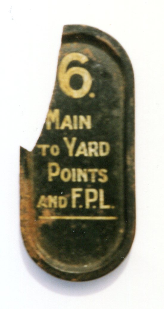 One
surviving L&BR relic is a damaged example of one of the
lever description plates which would have
been fitted to the levers in Pilton signal-box, giving the lever number and
description of its function; in this case the plate was from lever
6, painted black and bearing the
legend in white 'Main to Yard Points and F.P.L.'
(click picture for larger image). This indicates that it worked the facing point marked 'C'
on the outline diagram above, together with its 'economic'
Facing Point Lock (FPL). The plate makes no specific reference to the
associated trap point, but this is not necessarily unusual (a similar situation
occurred with the siding at Chelfham) and it is unlikely that in fact the trap point was worked by a separate lever. The identification of
lever 6, when read in conjunction with additional information in Col Yorke's
Inspection Report, helps to identify lever 5 as working the
Down Loop facing points (marked 'B'
on the outline diagram above).
One
surviving L&BR relic is a damaged example of one of the
lever description plates which would have
been fitted to the levers in Pilton signal-box, giving the lever number and
description of its function; in this case the plate was from lever
6, painted black and bearing the
legend in white 'Main to Yard Points and F.P.L.'
(click picture for larger image). This indicates that it worked the facing point marked 'C'
on the outline diagram above, together with its 'economic'
Facing Point Lock (FPL). The plate makes no specific reference to the
associated trap point, but this is not necessarily unusual (a similar situation
occurred with the siding at Chelfham) and it is unlikely that in fact the trap point was worked by a separate lever. The identification of
lever 6, when read in conjunction with additional information in Col Yorke's
Inspection Report, helps to identify lever 5 as working the
Down Loop facing points (marked 'B'
on the outline diagram above).
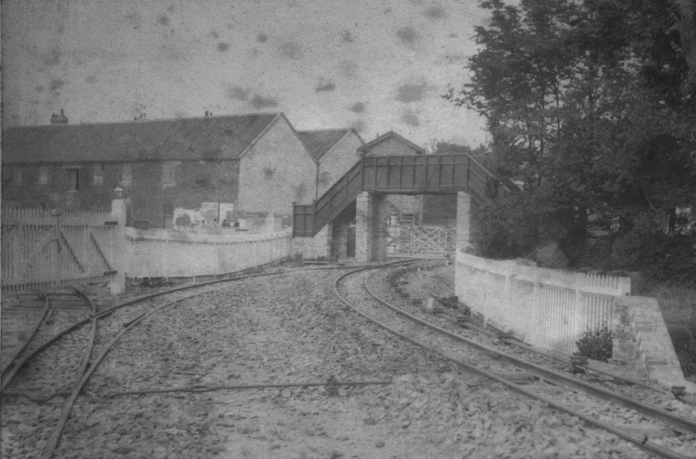 Pilton Quay siding
can be seen in an 1898 photo here (click for larger image) of the
original layout with the points at the Pilton end facing to Up trains.
[In the background can be seen also the footbridge (Bridge No 4) at
Pilton Causeway crossing in its original form and above that
the roof of the SB in its original tall version.] Despite its
proximity to the signal-box the siding was controlled by an uncovered EoD-pattern GF (believed
to have been just one lever) located on the Down side of
the line adjacent to the access point; this worked the facing point, its associated
'economic' FPL and the point in the siding (leading off towards the actual Quay) which
acted as a trap-point. The rod from latter point to the GF can be seen in
the foreground, crossing between the tracks before running back towards the GF
(alongside a different rod from the signal-box to Braunton Road
level-crossing) on the Up side of the line.
Pilton Quay siding
can be seen in an 1898 photo here (click for larger image) of the
original layout with the points at the Pilton end facing to Up trains.
[In the background can be seen also the footbridge (Bridge No 4) at
Pilton Causeway crossing in its original form and above that
the roof of the SB in its original tall version.] Despite its
proximity to the signal-box the siding was controlled by an uncovered EoD-pattern GF (believed
to have been just one lever) located on the Down side of
the line adjacent to the access point; this worked the facing point, its associated
'economic' FPL and the point in the siding (leading off towards the actual Quay) which
acted as a trap-point. The rod from latter point to the GF can be seen in
the foreground, crossing between the tracks before running back towards the GF
(alongside a different rod from the signal-box to Braunton Road
level-crossing) on the Up side of the line.
In the later layout, with the points at the Braunton Road end facing to Down trains, there was an adjacent GF which is believed to have been on the Down side of the line adjacent to the facing point (and it has been marked as such on the circa-1930 outline diagram for reference) but no conclusive photographic or map evidence is known. It is not known whether, when the layout was altered, the use of an 'economic' FPL was continued and the original 1-lever EoD GF was re-used, or whether a separate FPL was fitted and a new (possibly 2-lever) GF was provided. The later GF was unlocked by the single-line tablet for the Pilton - Barnstaple Town section and it is probable that the same control arrangement applied for the original GF.
|
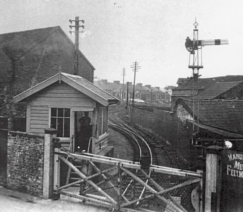
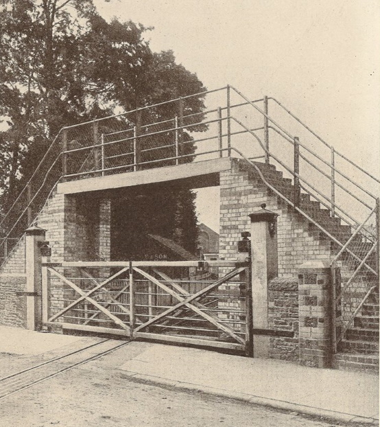
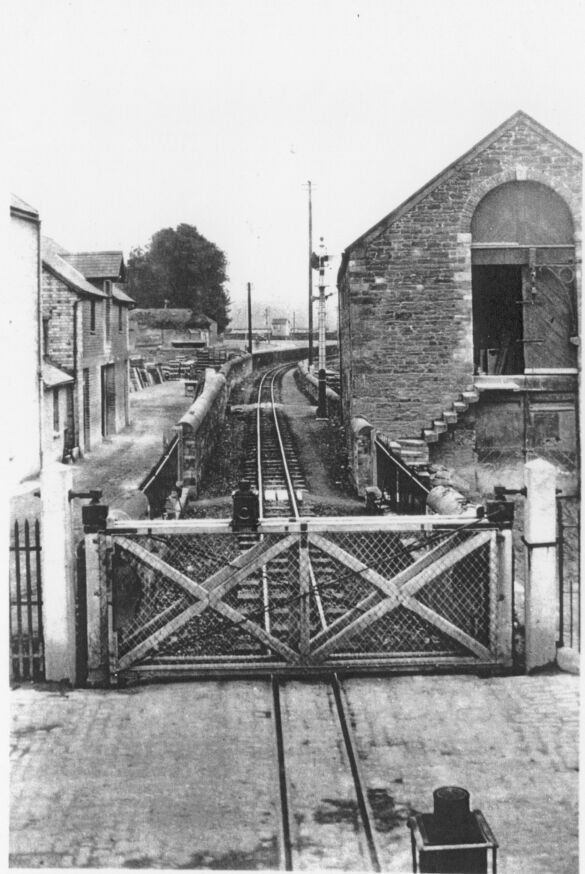
Pilton Causeway level-crossing was located immediately on the Town side of the signal-box and was equipped with a set of four wooden gates. Because the road was much wider than the railway the gates, which met in the middle when closed across the road, overlapped each other when closed across the railway as can be seen in the image on the right (click for larger view). The gates would have been worked by hand on the ground by the signalman and locked in position across the road by a lever in the signal-box lever-frame. Only when the gates were locked safely across the road would the lever-frame interlocking permit the signalman to clear any signals for the passage of trains over the level-crossing. There was a footbridge (Bridge No 4) over the line immediately on the Town side of the road, which was constructed originally with brick piers and wooden deck and stairs (as seen here); at some date prior to 1923 it was rebuilt with a reinforced concrete deck (designed by the British Reinforced Concrete Engineering Co Ltd) as seen in the image here. Curiously the ornate iron caps which adorned the main gate-posts bore the initials BWH&A of the nearby Bideford, Westward Ho! & Appledore Railway, which closed in 1917. |
 |
|
| Pilton Causeway Crossing |
|
Braunton Road level-crossing was about 100 yards away towards the Town station, so it had its own crossing-keeper to work the gates locally by hand. As at Pilton Causeway there were four gates which met in the middle when closed across the road, but overlapped when closed across the railway. The gates at Braunton Road were locked from Pilton signal-box, but it is not known whether they were bolted directly by a lever at Pilton, or by a separate ground-frame adjacent to the crossing which then was locked from the signal-box; both methods are possible, but in the absence of any evidence for another GF the simpler option of direct bolting from the signal-box seems more likely. This photograph (click for larger image), looking towards the Town station in August 1926, shows the gates closed across the railway; the rear of the Down Home signal can be seen (at that time only with one arm), with the L&BR Barnstaple Town signal-box in the far distance. A crossing-keeper would have been needed on duty throughout the working day at Braunton Road, so it is to be expected that some form of shelter was provided for him, and indeed an inquest report (click here for a transcript) of a staff fatality at the crossing in 1910 does mention a 'hut'. There is plan evidence that this was constructed as a 'lean-to' against one of the piers supporting the footbridge (Bridge No 1) which crossed over the line immediately on the Pilton side of the road. The report also makes reference to the crossing-keeper giving hand-signals to the Pilton signalman to indicate that the gates were closed, but in Southern Railway days the Braunton Road crossing-keeper and Pilton signalman communicated by means of bell signals. |
 |
|
| Braunton Road Crossing | ||
According to SR Signal Instruction No 4A of 1925, at that time the bell signals used between Pilton signal-box and the Braunton Road crossing-keeper were as shown in the table on the right. The Instruction required the Pilton signalman to send the appropriate code to the crossing-keeper three minutes before a train was due to pass over the level-crossing. However by 1930 the bell codes had been changed and the warning time reduced to two minutes - click here to read the later SR instructions (No 685.B.1929). |
|
|||||||||||||
There is evidence from SR records that by 1927 there was an electric treadle located on the single line between the entrance to Pilton Quay siding and the level-crossing at Pilton Causeway, but there is no information available as to the date of its installation or what function, if any, it might have served relevant to the signalling at Pilton. Instead it is thought probable that in fact this treadle was relevant to the working at Barnstaple Town and may not have been installed until the SR period as described here.
© CJL Osment 2002-2025
Acknowledgements to Michael Bishop
for archive information.
No 6 plate photograph courtesy David Hudson,
Pilton Quay siding photograph courtesy Tony Nicholson, OS map extract reproduced with permission of the National Library of Scotland, all other images WCRA collection.
| Interested in
the Lynton & Barnstaple Railway? Then why not join the Lynton & Barnstaple Railway Trust and help to re-build England's premier narrow-gauge line? |
| Introduction | Basic Layout | Signal Box | Signals | Points | Quay Siding | Level Crossings | Treadle |
|
|
|||||||
| © West Country Railway Archives 2002 Page last updated: 13 August 2025 |
URL:
E-Mail: |
||||||


