


 |
Lynton and Barnstaple Railway Signalling at the Intermediate Stations Chelfham, Bratton Fleming, Blackmoor, Woody Bay |
|
||||||||
|
||||||||||
This page describes the signalling at the main intermediate stations of the former narrow-gauge Lynton & Barnstaple Railway (L&BR). Please see the separate Introduction to L&BR Signalling page for background information and details of other pages on RailWest about the signalling of the L&BR. Click here for more general historical details about the L&BR and a Bibliography.
Passing-loops were provided at the four main intermediate stations on the line, namely Chelfham, Bratton Fleming, Blackmoor and Woody Bay. There was also a passing-loop (but no station) at Pilton (on the outskirts of Barnstaple, where the L&BR had their locomotive and carriage works), but that location is the subject of a separate page in RailWest. There are also separate pages for the terminal stations at Barnstaple and Lynton, as well as a page describing the actual L&BR signals themselves.
 |
 |
|
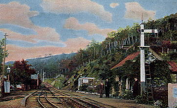
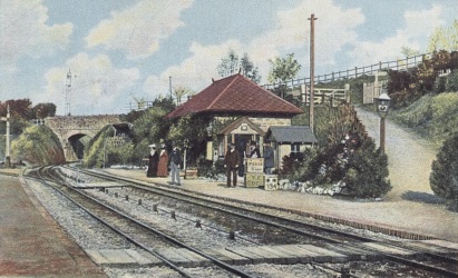
| Chelfham station looking north circa-1900 | Bratton Fleming station looking north circa-1900 |
There was no signalling at any of the later halts, namely Snapper, Parracombe and Caffyns. The Board of Trade Inspection Report produced by Colonel Yorke in 1898 does mention that "...there is a siding connection at Parracombe which is not yet brought into use...the points are at present padlocked and spiked...", but that siding was not at the same location as the later halt. It was located on the Up side of the line some distance north of the later halt, with a connection facing to Up trains, but it would appear that the actual siding was never installed and presumably the points were removed soon after the railway opened.
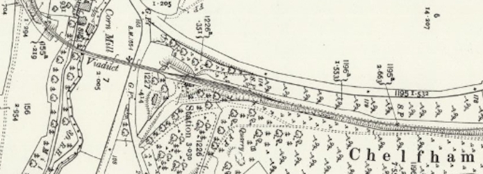
Note: all maps on this page are extracts from Ordnance Survey (OS) 25" maps revised in 1903 and published in 1904; they are reproduced here with permission of the National Library of Scotland (NLS). Click on any of the map images for a link to the relevant OS sheet online at the NLS.
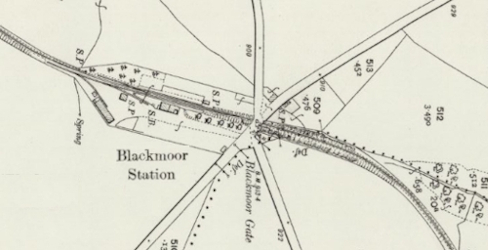
The four main intermediate stations were almost identical in their basic layout, each consisting of a passing-loop and a single connection providing access to a siding (or set of sidings). There was an exception to this general arrangement at Blackmoor, where there was an additional siding connection in the Down loop, but this was not part of the original layout. A further commonality in design can be seen in the fact that, with the exception of Chelfham and the additional Down siding at Blackmoor, all the sidings connections were made by facing points, something which at one time would have been carefully avoided. In later years the provision of signals was identical at all four locations, consisting merely of a Home and Starting signal in each direction, although the original arrangements were slightly different. Even the lever-frames appear to have been identical in size, being quoted by Col Yorke as 7 levers at each location.
The intermediate passing-loops may seem to have been signalled in a simple and straightforward manner, but there are a few interesting points of note and some queries to be raised. Col Yorke reported at the time of his Inspection that Starting signals were not provided at the intermediate loops, but he did not consider the expense of providing such signals was necessary for "...a line of narrow gauge and light traffic...". (An early photograph of Bratton Fleming station shows the passing-loop without any starting signals.) The L&BR used 'economic' Facing Point Locks (FPL) whereby the FPL was operated from the same lever as the point. This arrangement gives an initial requirement of only 5 working levers at each loop (2 x Home signals, 2 x loop facing points, plus 1 x siding point) and this matches the Inspection Report details given for Chelfham, Blackmoor and Woody Bay. It is curious therefore that Col Yorke mentioned six different lever numbers when asking in his Report for some interlocking modifications at Chelfham. After a while however the L&BR decided to provide Starting signals at the loops after all, and they wrote to the BoT in early 1899 to advise them that this had been done; their letter was accompanied by a drawing showing the revised arrangements at the four passing-loops (National Archives file MT6/876/8). The Inspection Report also contained the intriguing statement that "...distant signals only exist where home signals cannot be seen for a distance of a quarter of a mile ..." and it is believed that a very small number of distant signals were provided originally.
|
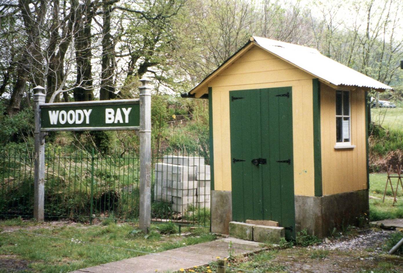
Apart from the two termini at Barnstaple and Lynton, and the passing-loop at Pilton, the intermediate station passing-loops were the only other locations on the L&BR to have signal-boxes and to be block posts for the single-line Electric Train Tablet (ETT) system. The signal-boxes at these loops were small wooden huts of identical design, sited in every case on the Up platform near to the station building. Woody Bay signal-box was recorded in the 1935 Sale Catalogue as measuring 6’x5’x7’. (Note the concrete plinth which had been added at some date as a result of timber rot.) In each signal-box the entrance door was in the front wall of the hut, with the lever-frame mounted 'back-to-track' against the rear wall. In Southern Railway (SR) days at least there would have been a signal diagram mounted on the rear wall behind the lever-frame, and it is believed that the SR also added the nameboard on the front wall above the door which appears in later photographs. The ETT instruments were housed in the station buildings; apart from the obvious lack of space in the 'huts', this arrangement probably reflected the fact that the signal-box was not manned permanently, but simply visited as and when necessary by the stationmaster or porter who also acted as signalman. |
 |
|
| Woody Bay Signal-Box (as restored 1999) |
All the four intermediate station signal-boxes were orientated in the same way, so that the Up direction was from left to right across the lever-frame. A common numbering sequence was used for all four lever-frames, as follows:-
| 1 | 2 | 3 | 4 | 5 | 6 | 7 | ||||||
| Up Starting Signal |
Up Home Signal |
Up Loop Points |
Siding Points |
Down Loop Points |
Down Home Signal |
Down Starting Signal |
Although the arrangements for laying-out a lever-frame varied between different railway companies and signalling contractors, in general the numbering sequence for a simple passing-loop would follow the pattern Distant - Home - Starting - Points - Starting - Home - Distant, whereas clearly on the L&BR the pattern was Starting - Home - Points - Home - Starting. This suggests that (with the exception of Bratton Fleming as mentioned below) levers 1 and 7 were the spare levers in the original installations, subsequently brought into use when Starting signals were added to avoid the extra cost of the additional locking alterations that would have been required in order to provide the 'normal' sequence. In turn this suggests that perhaps the spare levers were provided with future Distant signals in mind rather than Starting signals, as in the latter case one would have expected to see the Homes on 1 and 7, with 2 and 6 as the spares.
One small variation between the four signal-boxes concerns the method of working the siding connection. At Chelfham and Bratton Fleming the siding point and its associated exit trap-point were both worked from lever 4. However at Blackmoor and Woody Bay the facing points into the sidings were sufficiently close to the Down Loop facing points to be in effect a crossover and were worked together from lever 5, with lever 4 working the siding exit trap only. This arrangement had the advantage that it provided protection of the single line from any accidental over-run in the Up loop. There is a view of Blackmoor (by Knight) in which the siding point can be seen to lie set for the siding after the road has been set for a Down train and the Down Home is 'off'.
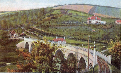
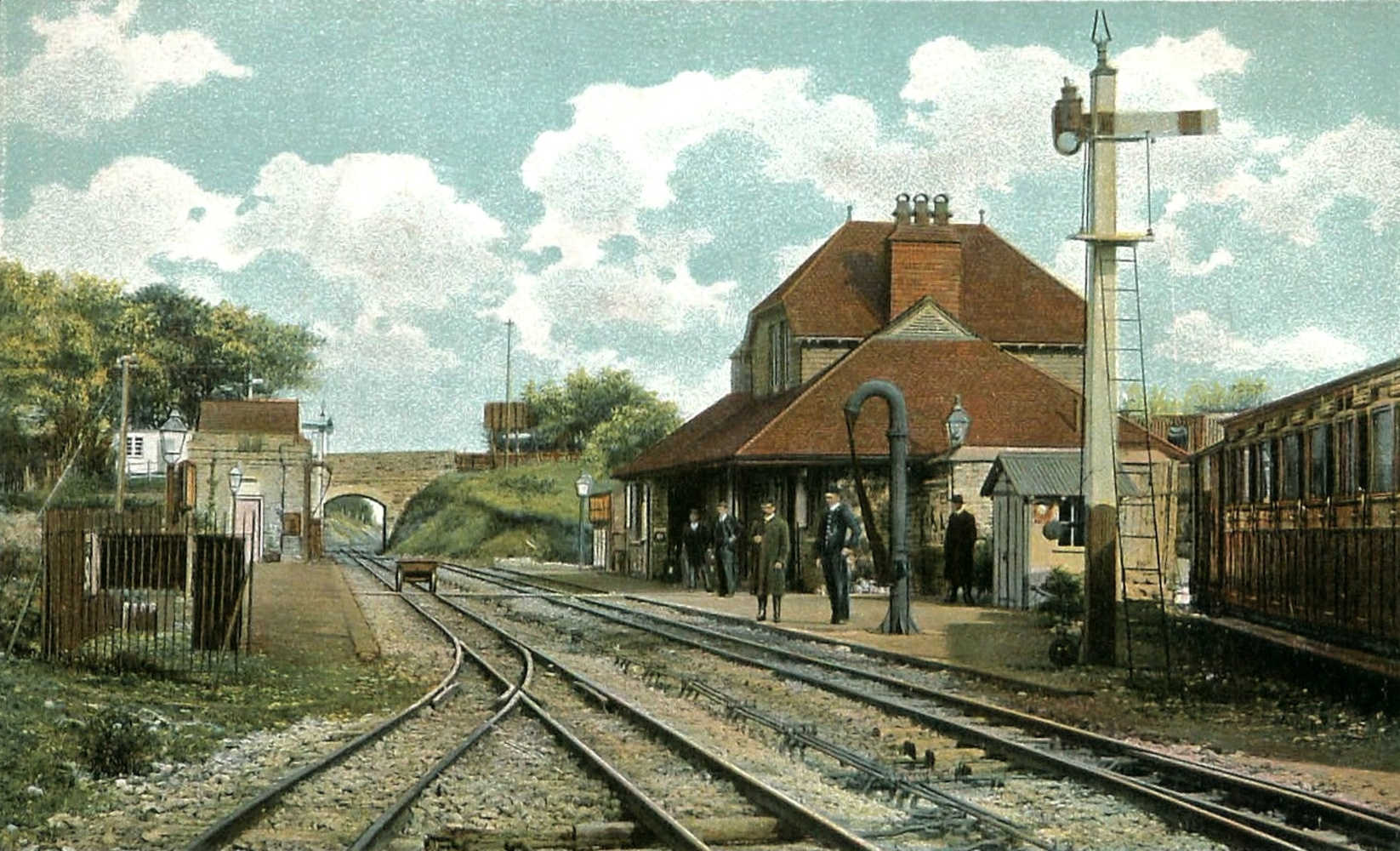
Chelfham station was laid out on roughly a south-north alignment, but for the purposes of this page the map below has been rotated such that south (to Barnstaple) is at the left-hand end and north (to Lynton) is at the right-hand end. The approach from Barnstaple was on a left-hand curve across Chelfham viaduct, eight arches across the Stoke Rivers valley and the largest structure on a narrow-gauge railway in England. The Down Home signal was sited at the approach to the Barnstaple end of the viaduct, as can be seen in the old coloured postcard view below. Chelfham was the 'odd one out' of the passing-loops, as it had a trailing connection into a single short siding at the Barnstaple end of the Down loop.
Note: according to 1898 records the Up Home was 130 yards from the signal-box, which would equate to a location just north of the facing points at the Lynton end (as seen in later photographs). However the OS map marks this signal (S.P) some distance further away towards Lynton. It is unclear if this is a labelling error in the map and the actual position of the signal is still under investigation.
 |
 |
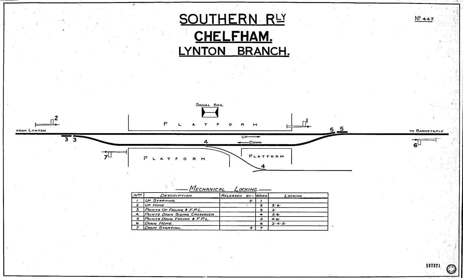
In 1923 the SR prepared a new signal diagram No 447 for the signal-box and a copy of this has survived (it is possible that this was just one of a set of new diagrams drawn for all the L&BR signal-boxes, but sadly no others have come to light yet). Comparison with a photograph (by Wheeler) of the inside of Chelfham signal-box, where it is possible to see most of the lever description plates, suggests that some of the descriptions assigned to each lever by the SR may have varied from those actually used in the signal-box. The Chelfham lever descriptions in the photograph appear to read as shown below (extrapolating from a similar photograph for Blackmoor for lever 1).
 |
 |
|
| Signal-box diagram for Chelfham 1923 Click diagram for larger image |
Representation of Chelfham's lever description plates |
In his 1898 Inspection Report Col Yorke asked at Chelfham for "No 5 lever not to release No 2", which suggests that, in the original installation without Starting signals, the Home signals were released by the reversal of the point at the exit end of the loop. This would be understandable, insofar as the Home signal protected that point in the absence of a Starting signal, but it would make for extra lever work when crossing trains. For example, having reversed the Down Facing points in order to clear the Up Home to admit an Up train into the loop, the points would have to be returned to normal in order to admit the Down train, then reversed again in order for the Up train to leave, with corresponding activity at the other end of the loop. Unfortunately the similar request for "No 6 lever not to release No 3" does not fit in with the later numbering arrangement, but if one could assume that the Colonel accidentally got his numbers reversed then the release of 6 by 3 matches the theory above exactly!
Signal alterations. The Down Home signal was renewed at an unknown date, but probably in the SR period, and the new signal had a lattice post. The Down Starting signal was replaced on 9-August-1927 (SR Signal Instruction No 20 of 1927) by one with a 17½' concrete post (only one of two such posts known on the L&BR, the other being at Blackmoor). (After the railway was closed this post was felled and left lying on the side of the embankment, where as late as 2015 it could be found still in the undergrowth! Since then it has been removed for preservation.) The Up Home signal was on the right-hand side of the line, but on 13-April-1926 (SR Signal Instruction No 14 of 1926) it was replaced by a signal on the opposite side of the line, which was placed part of the way up the side of the cutting. The original signal was quite tall, whereas the new signal had a much shorter wooden post, but because of its elevated location the arm was at roughly the same height above rail level as its predecessor. The Up Starting signal remained in use until the line closed in 1935, at which time it was the only survivor of the original Evans O'Donnell signals.
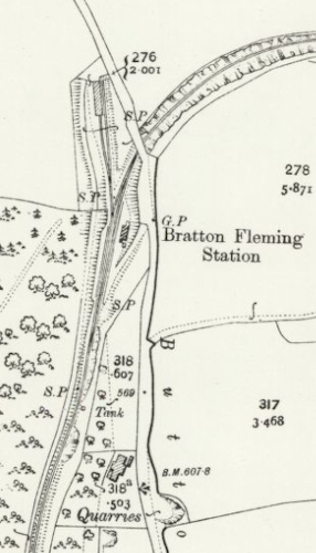 Bratton Fleming
station was laid out on roughly a south-north alignment, but
at the Lynton (north) end the line swung sharply to the right, passed under
Station Hill (Bridge 34) and then ran eastwards for some distance before turning
northwards to continue on towards Blackmoor. The sidings were accessed by a
facing connection off the Down loop near the Lynton end and diverged on roughly a
northwards alignment to run into a goods yard that was sited on level ground
to the north-west of Bridge 34. The connection into the goods yard passed
through the Lynton end of the Down Platform and then through a gateway in the
boundary fence at the rear of the platform, although in later years both the
gate and the fence at the north end of the platform were removed.
Bratton Fleming
station was laid out on roughly a south-north alignment, but
at the Lynton (north) end the line swung sharply to the right, passed under
Station Hill (Bridge 34) and then ran eastwards for some distance before turning
northwards to continue on towards Blackmoor. The sidings were accessed by a
facing connection off the Down loop near the Lynton end and diverged on roughly a
northwards alignment to run into a goods yard that was sited on level ground
to the north-west of Bridge 34. The connection into the goods yard passed
through the Lynton end of the Down Platform and then through a gateway in the
boundary fence at the rear of the platform, although in later years both the
gate and the fence at the north end of the platform were removed.
Immediately inside the yard there was a single-blade trap-point (worked by lever 4 in conjunction with siding facing point) to protect the Down loop and then a hand-point which connected the two sidings. This point was worked by a 'throw-over' hand-lever which originally was sited on the outside of the siding, but at some unknown date it was moved to a location between the siding and the Down loop. (This lever is believed to be of the same pattern as those used for the siding points in the yard at Pilton, as it formed part of the same 1897 equipment order.) The left-hand (shorter) siding ran as far as (but not through) the near-end wall of the good shed, while the right-hand (longer) siding ran past the outside of the goods shed on its east side as far as its further end.
Col Yorke listed Bratton Fleming as having seven working levers with no spares (possibly the only L&BR signal-box to have no spare levers initially other than maybe Lynton) and there is evidence from 1898 records that Bratton Fleming was equipped originally with working Distant signals in both directions. An early photograph of the station (which pre-dates the provision of Starting signals) shows two separate signal wire pulleys on each side of the Down Loop at the Lynton end - the Up Home would account for one wire and so the other surely was for the Up Distant. When Col Yorke re-inspected the line later in 1898 he did not object to a request from the L&BR to abolish the Distant signals at Bratton Fleming and they were not shown in the revised diagram sent to the BoT in 1899, so one may presume that they were abolished altogether rather than just converted to a 'fixed' form.
Note: The National Archives file MT6/876/8 includes a report for the BoT compiled by W Gamble (apparently an employee of the railway company) providing information in advance of the BoT Inspection on matters such as the location of all the signals etc. This report includes a (proposed) requirement for the Up Distant and Down Distant signals to be 'repeated' - in other words, to have electrical indicators installed in the signal-box to show whether the signal arms were 'on' or 'off'. It is not known if such indicators were actually provided at Bratton Fleming nor, if so, of what pattern.
The Down Home was replaced on 6-October-1926 (SR Signal Instruction No 32 of 1926) by a new signal 8 yards nearer to the station, but the type of new post is unknown. At an unknown date in SR days the Up Home was replaced by a new signal with a lattice post, like its predecessor a tall post on the right-hand side of the line and mounted on top of the cutting just north of the road over-bridge No 34. Nothing is known about any possible alterations to the two Starting signals.
Abolition of Loop. The passing-loop at Bratton Fleming was taken out of use as an economy measure on 16-June-1931 (SR Signal Instruction No 20 of 1931), after which all trains used the former Up loop and platform. All the signals were abolished, but the signal-box was retained as a ground-frame (GF) to work the points. The box ceased to be a block-post, the ETT section becoming Chelfham - Blackmoor, and thereafter the lever-frame in the box was released by a tablet for that section. The Signal Instruction stated that "A ground frame...will be provided in the existing signal box....", which might imply that the GF was a new installation, but in the interests of economy it would seem more probable that the existing lever-frame was retained. The Instruction also stated that "Vehicles must not be left standing on the existing down loop line (to be used in future as a siding) between Nos 3 and 5 points, but must be berthed inside No 4 catch points in the down siding", which would suggest that trap points were not provided at the exits from the former down loop. The fact that those point numbers matched the original installation would seem to confirm the presumption that the GF mentioned in the Instruction was indeed the original lever-frame.
 New
Ground-Frame. On 25-May-1932 (SR Signal Instruction No 20 of 1932) the old
Down loop was abolished and the siding was connected directly into the former Up
loop, now the single-line, by a new point (facing to Down trains) 24 yards on
the Chelfham side of the former signal-box. This point was provided with an
ordinary (non-economic) FPL. The existing trap-point in the siding was relocated
or replaced at the clearance point of the new connection with the
single line. At the same time the existing GF in the former signal-box was
replaced by a new, uncovered GF located on the platform close to the Barnstaple
end and positioned at right-angles to the track so that the operator faced towards Lynton. From a partial
photographic view the GF seems to have been of the Stevens-pattern 'knee' type
favoured by the SR and it was equipped with 3 levers, working as follows:-
1 - Points 2 - FPL 3 - Release . Lever 3 was fitted with a mechanical lock worked by the tablets for the Chelfham - Blackmoor section. This was an unusually generous provision for an 'economy' alteration, as the
SR normally did not bother with a separate Release lever in such cases, but merely fitted the ETT release lock directly to the FPL lever.
New
Ground-Frame. On 25-May-1932 (SR Signal Instruction No 20 of 1932) the old
Down loop was abolished and the siding was connected directly into the former Up
loop, now the single-line, by a new point (facing to Down trains) 24 yards on
the Chelfham side of the former signal-box. This point was provided with an
ordinary (non-economic) FPL. The existing trap-point in the siding was relocated
or replaced at the clearance point of the new connection with the
single line. At the same time the existing GF in the former signal-box was
replaced by a new, uncovered GF located on the platform close to the Barnstaple
end and positioned at right-angles to the track so that the operator faced towards Lynton. From a partial
photographic view the GF seems to have been of the Stevens-pattern 'knee' type
favoured by the SR and it was equipped with 3 levers, working as follows:-
1 - Points 2 - FPL 3 - Release . Lever 3 was fitted with a mechanical lock worked by the tablets for the Chelfham - Blackmoor section. This was an unusually generous provision for an 'economy' alteration, as the
SR normally did not bother with a separate Release lever in such cases, but merely fitted the ETT release lock directly to the FPL lever.
Blackmoor station was laid out on roughly a south-west to north-east alignment, but for the purposes of this page the map below has been rotated such that south (to Barnstaple) is at the left-hand end and north (to Lynton) is at the right-hand end. The old coloured postcard image shows a view looking northwards towards Lynton.
 |
 |
 At Blackmoor station a facing connection at the Barnstaple end of the Up Loop
led to a headshunt, which gave access to two sidings. There was also a short siding off the Down loop, which
may have been used initially to stable an extra coach provided in
connection with traffic for a horse coach link to Ilfracombe. It is unclear
exactly when this siding was installed, but it is believed to have been in place
within a short time of the opening of the line. This siding connection was not
worked directly from the signal-box, but by a separate 1-lever GF situated at
the Barnstaple end of the Down platform and mounted with its lever parallel to
the track. Perhaps the provision of a separate GF was seen as a cheaper or
easier option than the extension and re-locking of the signal-box lever-frame?
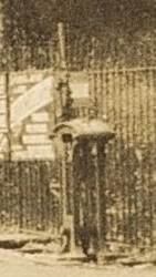
Despite its location this GF is very elusive in the photographic record and only
a few images are known - the picture shown here is a hazy
enlargement from a distant view.
At Blackmoor station a facing connection at the Barnstaple end of the Up Loop
led to a headshunt, which gave access to two sidings. There was also a short siding off the Down loop, which
may have been used initially to stable an extra coach provided in
connection with traffic for a horse coach link to Ilfracombe. It is unclear
exactly when this siding was installed, but it is believed to have been in place
within a short time of the opening of the line. This siding connection was not
worked directly from the signal-box, but by a separate 1-lever GF situated at
the Barnstaple end of the Down platform and mounted with its lever parallel to
the track. Perhaps the provision of a separate GF was seen as a cheaper or
easier option than the extension and re-locking of the signal-box lever-frame?
Despite its location this GF is very elusive in the photographic record and only
a few images are known - the picture shown here is a hazy
enlargement from a distant view.
There is some uncertainty over the manner by which this GF was locked, as some undated sources state that it was released by a key from the signal-box, whereas 1930 SR records specify an ETT release (presumably using a tablet for the section to Bratton Fleming). The use of tablet release on a GF that was within station limits seems most unusual (but not unknown) and a key release would seem more appropriate, probably an Annetts key interlocked in the signal-box lever-frame so that its withdrawal would lock the Down Home signal. Perhaps the control method was altered at some unknown date? Both the Down Siding and its GF were abolished on 19-August-1930 (SR Signal Instruction No 35 of 1930) and certainly the Instruction mentions abolition of a 'tablet lock'.
Signal alterations. The Down Home signal was still in its original form in mid-1927, but by 1935 it had been replaced by a new signal with a lattice post. The Down Starting was replaced on 14-August-1926 (SR Signal Instruction No 14 of 1926) by a new signal with a lattice post, which was 4' higher than its predecessor. In a similar manner to Bratton Fleming, the original Up Home had been mounted on the right-hand side of the line on top of the embankment just north of the road over-bridge No 56. However on 17-September-1929 (SR Signal Instruction No 35 of 1929) it was replaced by a new signal on the left-hand side of the line on a 30' lattice post 10 yards further away from the signal-box. The Up Starting was replaced sometime between 1924 and mid-1927 by a new signal with a concrete post (the only other concrete post known on the L&BR apart from the example at Chelfham).
[Note: there is a concrete post at the site of the former Blackmoor station which may be the remains of the Up Starting signal, albeit now in a different location. The former station is now the Old Station Inn, which is owned by a subsidiary company of the Lynton & Barnstaple Railway Trust.]
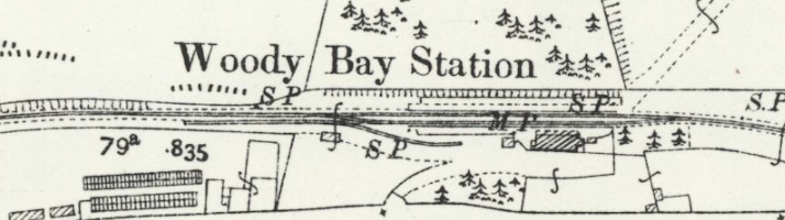
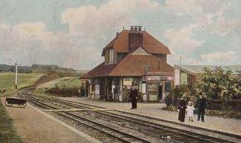
Despite its name, Woody Bay station was actually at Martinhoe Cross, about 1½ miles inland from the actual Woody Bay and several hundred feet higher up on Exmoor. Overall the L&BR ran on roughly a south-west to north-east alignment, so it may come as a surprise to discover that Woody Bay station was laid out almost entirely on an west-east alignment, a testament perhaps to the tortuous route of the line as it followed the contours of Exmoor. In the map shown below west (to Barnstaple) is to the left and east (to Lynton) is to the right. The old colour postcard image shows a view looking eastwards towards Lynton.
 |
 |
The layout at Woody Bay was essentially the same as Blackmoor, except that there was no additional siding on the Down side. A facing connection at the Barnstaple end of the Up Loop led to a headshunt, which gave access to one siding. The Down Home signal was replaced at some unknown date between 1925 (approximately) and mid-1933, by which time it had a SR-style rail-built post. The Down Starting was replaced at some unknown date between 1915 and 1927, by which time it was a wooden post signal in a similar style to those which were erected at Lynton in late 1924, so it is possible that it was an early SR replacement. The Up Starting was replaced by a new signal with a SR-style rail-built post at an unknown date in the early 1930s. The Up Home was replaced on 19-December-1934 (SR Signal Instruction No 47 of 1934) by a new signal with a SR-style rail-built post; this was the only signal on the L&BR to be fitted with an upper-quadrant arm, and also the last known replacement signal on the line.
Apart from the addition of Starting signals in early 1899 and the 1930s alterations at Bratton Fleming, the basic signalling at the intermediate station passing-loops remained virtually unchanged throughout the life of the L&BR until the closure of the line. However most of the actual signals at the intermediate stations were replaced or modified in a variety of ways at different times (probably due mainly to routine maintenance and repair) as described above, and these changes are listed also in a separate L&BR Signal Register. There can not have been many (if any) other railways where a (virtually) identical arrangement was provided at four consecutive passing-loops.
Two of the original L&BR signal-box 'huts' still exist today, at Chelfham and Woody Bay, but without their original lever-frames. The signal-box at Woody Bay has been restored by the Lynton & Barnstaple Railway Trust (L&BRT) and brought back into operational use with a replacement 9-lever Stevens 'knee' type frame (as used by the SR); three of the SR-era signals have been re-created in roughly their original form and locations. The signal-box and station at Chelfham are a longer-term restoration project, but the signal-box has been fitted with a replacement 7-lever Stevens 'knee' type frame (not yet operational) and work is in hand to erect reproductions of the original Evans O'Donnell signals in their original locations (of which 3 have been done as of mid-2025).
What is believed to have been the hut from Blackmoor was moved to a location beside the trackbed some distance north of that station, where it was used for farm storage; it was photographed there in 1967 in a dilapidated condition and no longer exists (probably burnt as firewood). The hut from Bratton Fleming was moved to the well which supplied the station water tank when an electric pump was installed to supply the nearby Quarry House; sadly some years later a tree fell on it during some clearance work and it was sold off as a pile of firewood!
[Note: the lever-frame now at Woody Bay was formerly a 10-lever ground-frame at Halwill Junction, reduced to 9 levers in order to fit the L&BR hut. The 7-lever frame now at Chelfham was manufactured by the Railway Signal Company and was obtained by the L&BRT from the collection of the former Hampshire Narrow Gauge Railway Trust at Bursledon Brickworks, but its original operational location is unknown.]
© CJL Osment 1999-2025
Acknowledgements to Michael Bishop, Nigel Thompson and the Signalling Record Society
for archive information.
Chelfham lever descriptions image courtesy of
John Hinson, Chelfham SB
diagram courtesy
Signalling Record Society,
OS map extracts reproduced with permission of the National Library of Scotland, all other images WCRA collection.
| Interested in
the Lynton & Barnstaple Railway? Then why not join the Lynton & Barnstaple Railway Trust and help to re-build England's premier narrow-gauge line? |
| Basic Layout | Signal-Boxes | Lever-Frames | Chelfham | Bratton Fleming | Blackmoor | Woody Bay | Conclusion |
| © West Country Railway Archives 2010 Page last updated: 08 August 2025 |
URL:
E-Mail: |
||||||


