


 |
Somerset &
Dorset Joint Railway Signalling at Bailey Gate |
|
|||||||
|
|||||||||
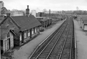
The railway station at Bailey Gate was located in the county of Dorset at the southern end of the 'main line' of the Somerset & Dorset Joint Railway (S&DJR). The southern part of the S&DJR was constructed originally by the Dorset Central Railway (DCR) as a single-track line running north-westwards from Wimborne to Blandford, but later the line through Bailey Gate was converted to double-track. When the station was opened on 1-November-1860 it was named Sturminster Marshall originally, but in 1863 it was renamed Bailey Gate after the turnpike gate on the nearby main road. (The renaming was done probably to avoid confusion after a new station opened at Sturminster Newton when the DCR extended northwards from Blandford.) Bailey Gate was the first station north of Wimborne and had Up and Down platforms, with a goods yard on the Down side behind the station and another siding on the Up side. Adjacent to the goods yard was a dairy, which provided regular milk traffic to the railway throughout its existence. A local road crossed the railway by an over-bridge No 220 immediately to the north of the platforms.
 |
 |
 |
||
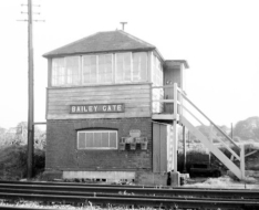
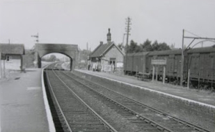
| Bailey Gate station looking south | Bailey Gate signal-box | Bailey Gate station looking north |
The earliest known reference to any signalling at Bailey Gate is a mention in the Minutes of the S&DJR Officers' meeting on 8-November-1876 (National Archives (TNA) file RAIL/626/16) of the decision to provide a signal-box there. Minute No 389 stated "Box to be fixed at the Wimborne end of the up platform at Bailey Gate and signals worked from it. Points to be bolt-locked. Estimated cost £130". At that time there was probably only a limited number of passing-loops on the ex-DCR single-line (see the RailWest page on S&DJR Early Signalling), but the reference to 'up platform' would seem to imply there was already a passing-loop with separate Up and Down platforms at Bailey Gate. It is probable also that Bailey Gate was equipped with a number of disc-and-crossbar signals at that time, as the late CR Clinker records (from an unknown source) that all such signals were replaced by semaphore signals on 10-February-1879. Clinker recorded the same date from S&DJR Signalling Instruction No 20 (of which no copy has been sighted yet for confirmation) for the opening of a new signal-box (SB) at Bailey Gate, which the Signalling Record Society lists as containing a 20-lever interlocking frame. At that time the single-line block sections Blandford - Bailey Gate and Bailey Gate - Wimborne Junction would have been worked by 'block telegraph' without any form of physical train staff.
 S&DJR trains originally had to reverse at Wimborne in order to
run over the London & South
Western Railway (L&SWR) to Bournemouth. To ease this problem a new
'cut-off' line was constructed eventually, which left the S&DJR route at
Corfe
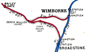
Mullen (about 2 miles down the line from Bailey Gate) and ran south-eastwards to join the L&SWR at
Broadstone Junction. Known officially as the 'Poole & Bournemouth Junction Railway',
the new line was brought into use for goods traffic on 14-December-1885, but
reportedly did not open for passenger traffic until 1-November-1886 (see
below). Although the actual
divergence from the ex-DCR route was at Corfe Mullen there was no
physical junction there; instead the Wimborne and Broadstone lines continued
north-westwards as parallel single-lines as far as Bailey Gate, where
the actual junction was made at the south end of the station. Bailey Gate then
became an important location in controlling the passage of trains onto or off
the southern end of the S&DJR.
S&DJR trains originally had to reverse at Wimborne in order to
run over the London & South
Western Railway (L&SWR) to Bournemouth. To ease this problem a new
'cut-off' line was constructed eventually, which left the S&DJR route at
Corfe
Mullen (about 2 miles down the line from Bailey Gate) and ran south-eastwards to join the L&SWR at
Broadstone Junction. Known officially as the 'Poole & Bournemouth Junction Railway',
the new line was brought into use for goods traffic on 14-December-1885, but
reportedly did not open for passenger traffic until 1-November-1886 (see
below). Although the actual
divergence from the ex-DCR route was at Corfe Mullen there was no
physical junction there; instead the Wimborne and Broadstone lines continued
north-westwards as parallel single-lines as far as Bailey Gate, where
the actual junction was made at the south end of the station. Bailey Gate then
became an important location in controlling the passage of trains onto or off
the southern end of the S&DJR.
[Note: the new line has been labelled variously as the 'Broadstone cut-off', the 'Corfe Mullen cut-off' or the 'Wimborne cut-off' by different historians. It could argued that the Wimborne epithet is the most appropriate, given that the line 'cut off' that part of the original route which went via Wimborne, but equally the Broadstone epithet could be used to describe a line which 'cut off' from the original route to go towards Broadstone.]
Initial Working. The early history of the new 'cut-off' line is frustratingly vague owing to the scarcity of relevant official records. According to Minute 3298 of the S&DJR Officers' Meeting of 29-December-1885 the line had been opened for goods traffic on 14th December that year. The same Minute also recorded that "...the opening of the line for passenger traffic has been sanctioned by the Board of Trade, to whom the usual undertaking has been given...with reference to the working of the line...on the electric tablet system...", in which case it is unclear why it is reported by most historians that the line was not used for passenger traffic until 1st November the following year. Apparently in the meantime, according to the S&DJR Working Timetable (WTT), it was used by only one goods train a day, which would seem a curious waste of a new and expensive asset that could have been used to improve traffic flow and increase line capacity.
It is not clear also exactly when the Electric Train Tablet (ETT) method of working was installed on the new line - was it already in place by the time that the undertaking mentioned above in Minute 3298 had been sent to the Board of Trade (BoT), or did that undertaking relate simply to an intention for future implementation? One may speculate that, as the BoT was interested primarily in lines carrying passenger trains, the 'cut-off' may have been opened for goods-only traffic under the 'block telegraph' system used elsewhere on the S&DJR at that time. However it is known that ETT working was in use on the new Bailey Gate - Broadstone single-line section by March 1886 (if not sooner), as it was listed as such in the S&DJR WTT Appendix 7 dated 1-March-1886. This was the first S&DJR single-line section to use ETT working and it would have been equipped with Tyer's No 1 ETT instruments.
[Note: the first use of ETT working (with Tyer's No 1 instruments) by the L&SWR had been on the nearby Salisbury & Dorset Junction Railway earlier in 1885, so that may have been an influence in the choice of ETT rather than Train Staff & Ticket working for the new 'cut off' line.]
New Signal Boxes. It would appear from map evidence and instructions in surviving S&DJR WTT Appendices for the 1886-1905 period that the original 1879 SB was superseded circa-1885 by two new SBs known as the 'Station' and 'Yard' boxes, probably in preparation for the opening of the new 'cut off' line. The 'Station' box was situated on the Up side of the line between the Blandford end of the Up platform and the road over-bridge, whilst the 'Yard' box was located on the Up side mid-way between the two sets of junction points at the Wimborne end of the station. (Click here to see the relevant instructions for these two boxes from the 1889 WTT Appendix.) However the various WTT Appendices details would suggest that only the 'Yard' box was a 'block post' controlling the single-line sections, with the 'Station' box being merely a ground-frame (GF) to work the points at the north end of the station. (Because of contemporary BoT restrictions on the distances for the mechanical operation of points, it was a feature of some S&DJR passing-loops at various dates for the points at one end to be worked by a GF locked from the SB.) Based on evidence from a later 1900 signal diagram (see below), it would appear that the 'Station' box was probably little more than a small ground-level hut with only a few levers; it is assumed that the 'Yard' box was a typical two-storey box, but it is unclear whether it was a new structure or simply the relocation of all or part of the original SB.
As mentioned above, the new line to Broadstone was the first single-line section of the S&DJR to be worked by ETT, being so listed in the WTT Appendix 7 dated 1-March-1886 (although the precise date of introduction is unknown) and used Tyer's No 1 ETT instruments. On 4-November-1886 the same method of working was introduced on the single-line sections to Blandford and Wimborne Junction (S&DJR box) to replace the previous 'block telegraph' system. It is presumed therefore that the ETT instrument for the single-line section to Blandford was housed in the 'Yard' box along with those for the sections to Wimborne Junction and Broadstone.
About 1¼ miles down the line from Bailey Gate was Bailey Gate Crossing and just under a further ½ mile beyond there was Corfe Mullen Crossing, both locations having crossing-keepers and gate-boxes. Prior to the subsequent opening of a new signal-box at Corfe Mullen Junction in 1905 (see below) it was the task of the signalman at Bailey Gate (presumably in the 'Yard' box) to inform the Corfe Mullen crossing-keeper of the approach of any Up or Down train on either line by means of the appropriate code on a warning bell. A 'repeater' bell was provided on the same circuit at Bailey Gate Crossing so that the crossing-keeper there could be made aware at the same time. Click here to see the appropriate instructions from the 1889 WTT Appendix.
Doubling the Line to Blandford
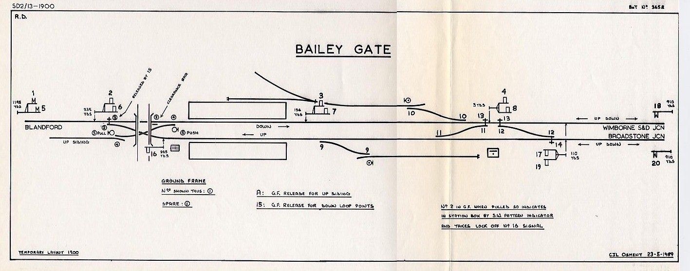
In 1900 a new temporary contractor's siding was provided at the north end of the station in connection with preparatory work for the doubling of the line to Blandford. This siding was on the Up side of the line, but accessed by a connection which crossed the end of the Up loop and trailed into the Down loop. The new siding was inspected for the BoT by Major Pringle, whose report dated 18-October-1900 is in TNA file MT6/971/9 with a signal diagram of which a sketch is shown below on the left. The old 'Station box' GF was utilised to control the new siding connection and its associated shunt signals, whilst in the 'Yard' signal-box a new lever 'A' was added to the left-hand end of the lever-frame to act as a release lever for the new siding.
It will be noted that, in addition to the 2-doll bracket immediately in rear of the new junction points 12 carrying the Down Advanced Starting signals (arms 4/8), both the Down Starting and Down Home signals further to the rear were also 2-doll brackets (arms 3/7 and 2/6 respectively), as also was the Down Distant signal (arms 1/5). The provision of 'splitting' stop signals in locations where there was only one possible route in advance of them towards the next stop signal appears to have arisen from an old practice if there was any pointwork in the intervening section of track between signals at the approach to a junction, possibly as a method for 'holding the route' to ensure that the junction points could not be changed in front of the approaching train. There was the advantage also of confirming which route was set to the driver of an approaching train. There is a brief reference to this practice on Page 140 (with Figure 346) of Raynar Wilson [3], which also alludes to the potential to save on extra signals on the intervening converging routes, but clearly that was not the result at Bailey Gate as there were no 'independent' shunt signals at the Wimborne end of the station in 1900 anyway.
 |
 |
|
| Bailey Gate Signal Diagram 1900 Click diagram for larger image |
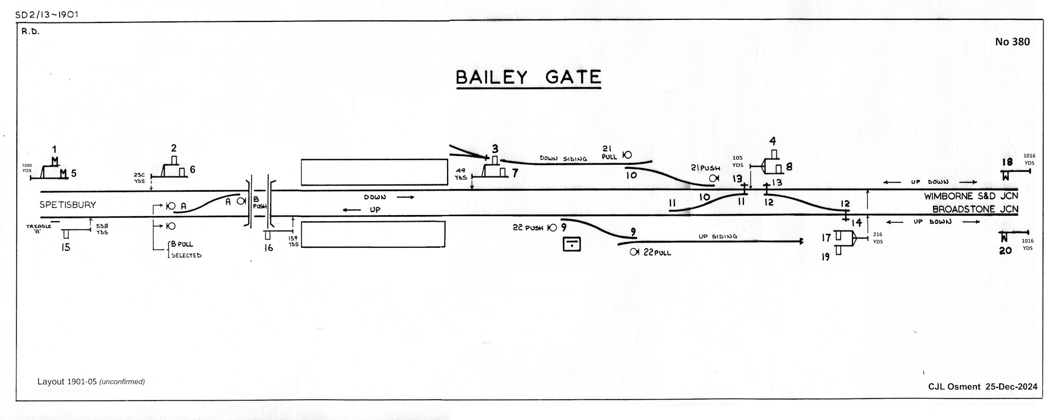
Bailey Gate Signal Diagram 1901-05 (unconfirmed) Click diagram for larger image |
The new double-track to Blandford (together with a new signal-box at the intermediate station at Spetisbury) was brought into use the following year, apparently on 29-April-1901; the late CR Clinker quoted that date from S&DJR Signal Instruction 140, but unfortunately no copy of that Instruction has been sighted. The new Up line replaced the former contractor's siding and all the pointwork by the road-bridge was replaced by a trailing crossover between the new Up and Down lines, with ground shunt signals at each end. A new Up Advanced Starting signal was added (worked by lever 15) and a treadle 'A' was provided some distance in advance of it to release a back-lock on lever 15, possibly because the signalman might not have had a very good view that the rear of an Up train had passed clear of that signal. (There is more information about back-locks in the RailWest page on S&DJR Sykes Instruments). ETT working between Blandford and Bailey Gate was abolished and the new double-track sections Blandford - Spetisbury - Bailey Gate were worked thereafter by the standard S&DJR block telegraph. The signal diagram on the right above shows the arrangements which are known to have existed by 1905, but are subject to some uncertainty as to the precise date of their introduction as described below.
[Note: there is a diagram similar to that shown above on the right for the revised layout post-1901 on page 86 of the OPC book [1], but it is labelled erroneously as being for the period from 1885 onwards (at which time the line to Blandford was still only single-track) and some of the signal distances do not match S&DJR records. Unfortunately the corresponding '1904' diagram in the revised edition of Pryer Vol 3 [2] also has some incorrect signal distances, but those have been corrected in the subsequent Errata list.]
Signal Box Mystery. After an initial inspection of the new double-track in April 1901 Major Pringle revisited the line on 15th June and reported (TNA file MT6/1012/9) that "...the old frame in the signal cabin contains 24 levers (two are numbered A & B) all in use, of which 3 are 'push & pull'...", a comment which may throw some light on a mystery about the signalling at Bailey Gate at that time. It is known from plan evidence that at some unknown date between 1900 and late 1904 the 'Yard' SB at the junction was replaced by another SB approximately 106 yards closer to the station, located on the Up side of the line south of the Up platform (apparently not in the same position as the 1879 SB). Points 9 were moved further south to make room for this new SB, but the capacity of the Up siding was maintained by extending it further southwards through the site of the former 'Yard' box. In its new location the SB was able to work the crossover at the Blandford end directly, so the 'Station' GF was abolished; lever 'A' was re-used to work the crossover and an additional lever 'B' was added to work the associated ground signals. (This was a 'push-pull' lever, which stood normally in a mid-way position; pulling the lever back worked one signal, pushing the lever forward worked a different signal.) At about the same time two more 'push-pull' levers (Nos 21 & 22) were added to control new ground signals for the existing sidings, superseding the previous 'point indicators' which had been provided at the siding exits only. If one presumes that the 3 push-pull levers noted by Major Pringle on 15-June-1901 were Nos B, 21 and 22, then it would appear that the abolition of the GF had taken place by that date, so was it perhaps the case also that the signal-box had been relocated by then? The unconfirmed diagram for the 1901-05 period shown above on the right is based therefore on the presumption that the relocation of the SB took place in early 1901.
All known photographs of a signal-box at Bailey Gate show a S&DJR Type 1 box in the post-1905 location. A Type 1 box would be consistent for a construction date of the late-1870s, whereas a Type 2 style would have been expected for a new 'Yard' box in 1885, or even a Type 3 structure for any new construction at the station circa-1901/05. The implication therefore is that the post-1905 SB re-used an older wooden superstructure on a new brick base, but it is a matter of conjecture whether that timber superstructure was from an older box at Bailey Gate or some other location. The lever-frame numbering post-1905 onwards equates to that of the 1900 layout as modified by known subsequent changes, so it would seem a reasonable assumption that the lever-frame from the 'Yard' box was re-used in the circa-1901 relocation.
Bailey Gate signal-box nameboard
In 1905 a new physical junction was constructed between the Wimborne and Broadstone lines at Corfe Mullen and a new Corfe Mullen Junction signal-box was opened there on 16th April that year. The junction at Bailey Gate was abolished and thereafter the two lines from Bailey Gate to Corfe Mullen Junction were worked as ordinary double-track and controlled by the standard S&DJR block telegraph for the new block section Bailey Gate - Corfe Mullen Junction. (It may be assumed that the two ETT instruments at Bailey Gate were transferred to the new signal-box at Corfe Mullen Junction, as the latter now controlled the shortened single-line sections to Broadstone and Wimborne Junction.) Facing crossover points 12 were removed, together with the associated Facing Point Locks 13 and 14, and also the redundant Down 'to Broadstone' signals (5, 6, 7, 8). In the Up direction the actual redundant 'from Wimborne' signals 17 and 18 were removed also, but their levers were re-used for the remaining Up Home and Up Distant (previously 19 and 20). The Down Advanced Starting signal (4) was renewed as a single straight post some distance further towards Corfe Mullen and ground signal 21PUSH was relocated to the Down line end of crossover 11. The diagram below is based on one in TNA file MT6/1373/4.
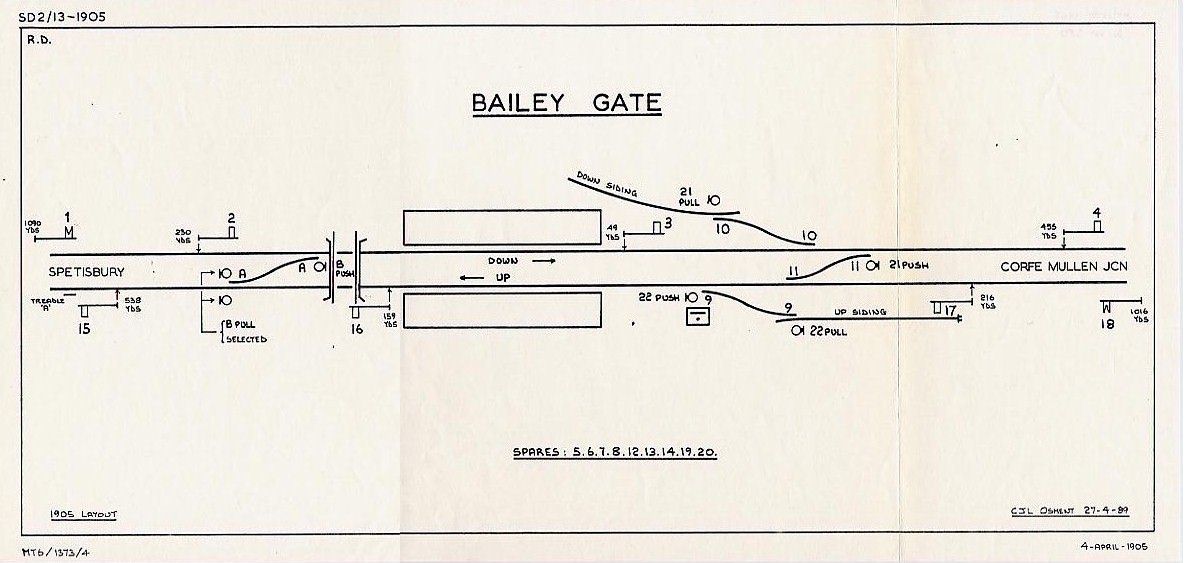
Bailey Gate Signal Diagram 1905
Click diagram for larger image
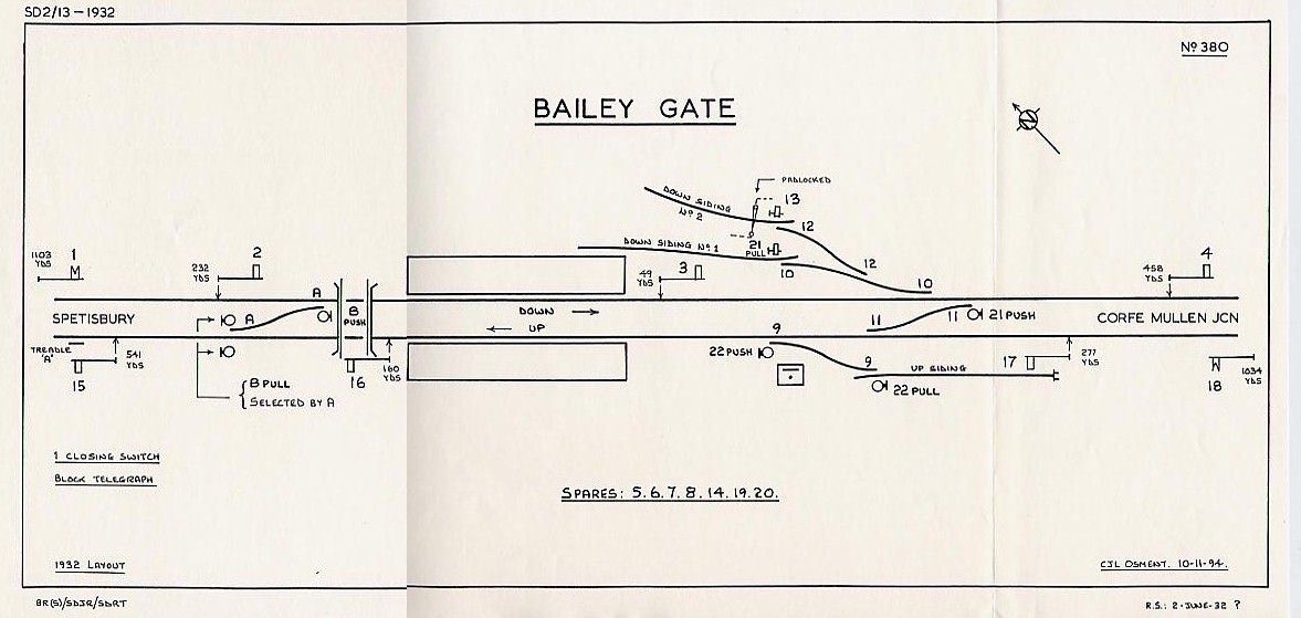
After the removal of the junction in 1905 the basic layout at Bailey Gate remained unchanged for many years, except for some minor alterations such as the relocation of the Up Home signal (17) about 50 yards further from the signal-box on 28-March-1915 (S&DJR Signal Instruction 248). Indeed a 1930 copy of the signal diagram shows the installation still to be essentially the same as the 1905 arrangements. However on 24-March-1932 (S&DJR Signal Instruction 322) a new 'Down Siding No 2' was provided, which was connected to the existing Down Siding (now renamed 'Down Siding No 1'), and this new connection utilised levers 12 and 13 for its points and ground signal.
 |
 |
|
| Bailey Gate Signal Diagram 1932 Click diagram for larger image |
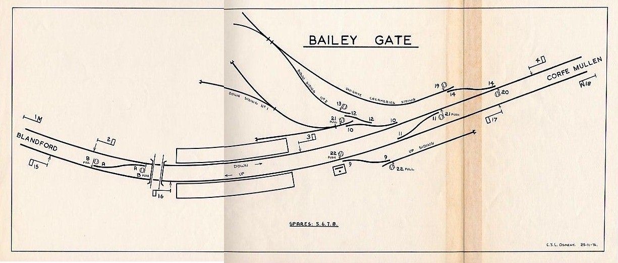
Bailey Gate Signal Diagram post-1955 Click diagram for larger image |
At some unknown date between 1932 and 1955 one of the pair of ground signals worked by lever BPULL was removed, with the remaining ground signal being used to control both routes. On 14-December-1952 (according to the relevant 'S&D Weekly Notice') ground signal 22PUSH was moved from outside the Up line into the 'six-foot' between the Up and Down lines. In early 1955 an additional 'United Dairies' siding was provided on the Down side with its own separate connection to the main running line, for which the points had been installed at an unknown date between 13th and 20th March; in connection with this alteration levers 14, 19 and 20 were brought into use for the new points and ground signals at an unknown date by late April.
 |
 |
|
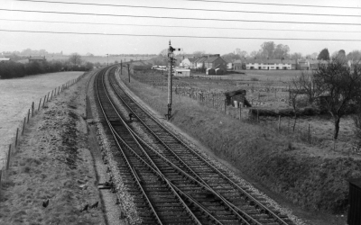
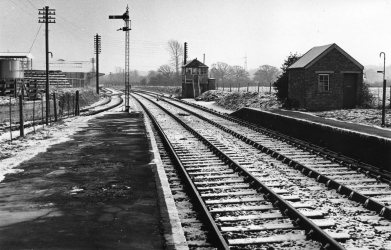
| Bailey Gate looking north from Bridge 220 in 1962 | Bailey Gate looking south from the station in 1966 |
The station was closed to general goods traffic on 5-April-1965, although the milk traffic continued. On 3-May-1965 the Up Siding was taken out-of-use, points 9 were disconnected from the lever-frame and clipped and padlocked, and signal 22PULL was abolished (Weekly Notice P/EW16). On 6-March-1966 passenger services ceased on the whole of the S&DJR and the station was closed to passengers. Although most of the S&DJR was now closed completely a few sections remained open for goods traffic and this included the line from Broadstone as far north as Blandford.
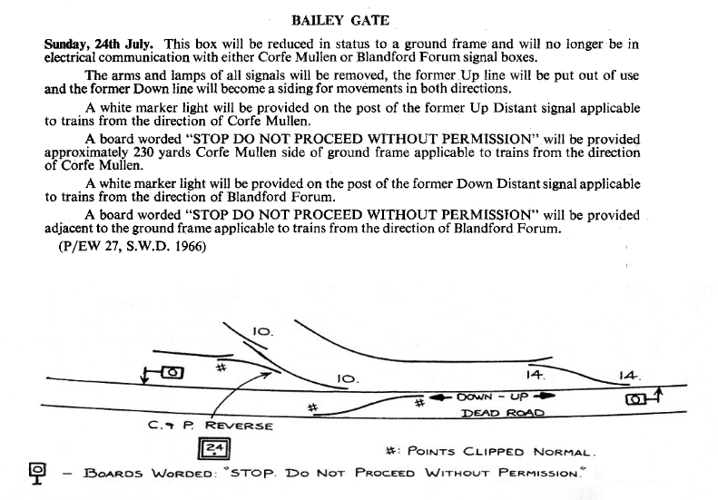 During 1966 the Up line was taken out of use and the Down line was worked thereafter as a siding for traffic in both
directions. The arms and lamps were removed from all the signals and white marker lights
provided on the posts of the former Distant signals (1 and 18). The signal-box
was reduced to ground-frame status and all its levers were taken out of use except
for 10 and 14, which controlled the two remaining sets of siding points. Down
Siding No 1 was clipped and padlocked out of use and the trap-point at the exit from Down
Siding No 2 was connected to lever 10 instead of 12. Warning boards worded 'STOP
DO NOT PROCEED WITHOUT PERMISSION' were erected at each end of the revised
layout to face approaching trains. Various dates have been quoted for this work,
but according to Weekly Notice P/EW27 it took place on 24-July-1966.
During 1966 the Up line was taken out of use and the Down line was worked thereafter as a siding for traffic in both
directions. The arms and lamps were removed from all the signals and white marker lights
provided on the posts of the former Distant signals (1 and 18). The signal-box
was reduced to ground-frame status and all its levers were taken out of use except
for 10 and 14, which controlled the two remaining sets of siding points. Down
Siding No 1 was clipped and padlocked out of use and the trap-point at the exit from Down
Siding No 2 was connected to lever 10 instead of 12. Warning boards worded 'STOP
DO NOT PROCEED WITHOUT PERMISSION' were erected at each end of the revised
layout to face approaching trains. Various dates have been quoted for this work,
but according to Weekly Notice P/EW27 it took place on 24-July-1966.
The ground-frame was closed on 7-May-1968 and the last remnant of the old S&DJR line in Dorset was closed finally on 6-January-1969.
Postscript...
Lifting of the track through Bailey Gate station took place during May and June 1970 and the former signal-box was demolished. All the station buildings had been demolished by 1973, the platforms by late 1988, and Bridge 220 in April 1992. All traces of Bailey Gate station have disappeared now under the development of an industrial estate, a new roundabout was built on the site of Bridge 220, and the trackbed northwards has been obliterated by a housing development.
© CJL Osment 2001-2024
Introduction station photographs courtesy Keith
Pfrangley collection, 1960s photographs John Eyers collection South
Western Circle, signal-box photographs WCRA collection.
|
© West Country Railway Archives 2001 Page last updated: 28 December 2024 |
URL:
E-Mail: |
||||||


