


 |
Somerset &
Dorset Joint Railway Signal Diagrams |
|
||||
|
||||||
This page provides general information about the Signal Diagrams which were provided for Signal Boxes and Ground Frames on the Somerset & Dorset Joint Railway (S&DJR). It covers the style and content of S&DJR signal diagrams, the various historical sources for such diagrams, and the availability (and reliability) of some published material. It is not intended to list or illustrate all known or surviving S&DJR signal diagrams, although some details are contained within the list of Diagram Numbers.
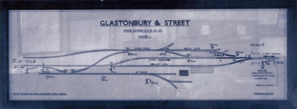
Glastonbury signal-box diagram circa-1962
| Diagram Content and Style |
The information in this section of RailWest notes has been drawn from the study of a large number of surviving S&DJR records, but there is no known complete collection of S&DJR diagrams from any of the different periods of railway's history. It has been possible to identify a number of general trends in the content and style of S&DJR diagrams, but - as with so many aspects of S&DJR signalling - there will always be the occasional examples of exceptions or variations from the 'norm'. It is not the intention to catalogue and describe every variation here, but occasional examples may be quoted by way of illustration of some of the eccentricities of the subject material.
The purpose of a signal diagram was to provide the signalman (or person operating a ground-frame) with basic details of the signalling installation at which he was working. This would usually be a signal-box (SB), or a manned ground-frame (GF) (such as at a level-crossing protected by signals), or an unmanned GF (such as at a siding at an intermediate location between stations). The diagram would show all the signals and points controlled by the SB or GF, other items such as level-crossings, and associated equipment such as treadles or track-circuits etc. Apart from the actual SB or GF itself any station platforms would be marked and sometimes other structures such as goods-sheds or loading-docks etc. Bridges over or under the railway might be included or not as was considered necessary.
Note: it is important to understand that signal diagrams were intended primarily to provide information necessary for the signalman to operate the installation in a safe manner. Signal diagrams were not track-plans; for example, although a diagram might show the points leading into a goods yard and any associated signals, it would not necessarily show every siding within that yard unless that level of detail was considered essential for the signalman. The diagrams were not drawn to scale, but simply as a schematic representation of the overall layout; for example, in many cases the main lines would be drawn as straight tracks even if in reality they were on a curve. The symbols used on diagrams to represent various items of equipment varied over time and would not be necessarily an accurate representation of what was 'on the ground', as the draughtsman would have worked from a sketch provided to him by the signal engineer rather than an actual 'site visit'. For example, the well-known 'wrong road' signal at Evercreech Junction North is shown on all known official diagram copies as being on a normal straight post, whereas in fact it was on a left-hand bracket. At least three different symbols were used over the years to represent ground-signals and it was not unknown for diagrams to have a mixture of at least two different styles as a result of later amendments, even if all the ground-signals at those locations were actually of the same pattern.
Most diagrams bore the railway's 'title' across the top, with the actual name of the signal-box or ground-frame below that. Some early diagrams from the 1890s were titled 'Somerset & Dorset Joint Railway' in full (one known example had 'Line' rather than 'Railway'), but thereafter the use of just the initials 'S.D.J.R.' seems to have become common. No examples are known of diagrams being titled 'L&SWR' or 'Southern Railway' or similar - the S&DJR seemed to keep its own identity in that respect. However after 1948 the titles on diagrams were changed to 'British Railways - Southern Region' or 'British Railways - Western Region' as relevant. As an example of a variation from the general practice, the initial 1914 diagram for Moorewood was titled 'S.D.J.R', but this was absent from a 1930 copy which had no company title at all. Similarly some GF diagrams did not have the actual GF name, but a description of the siding in terms of its purpose or ownership; for example, the diagram for Downside Siding was actually labelled 'Siding for Messrs Wainwright & Co near Winsor Hill'. Some older diagrams would have another line of text below the name which read 'Diagram of Signals etc' or similar, but as time progressed there was a tendency for the content of diagrams to become less 'elaborate' and more functional.
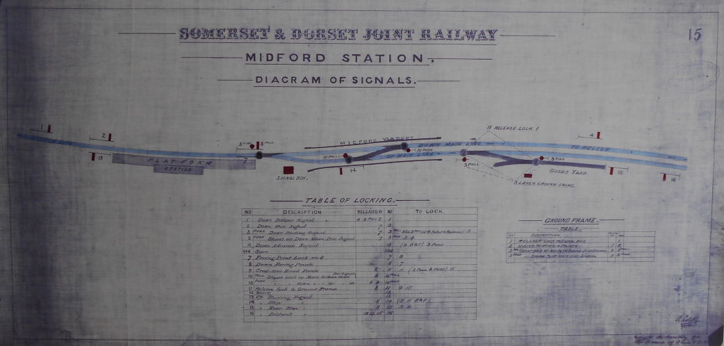
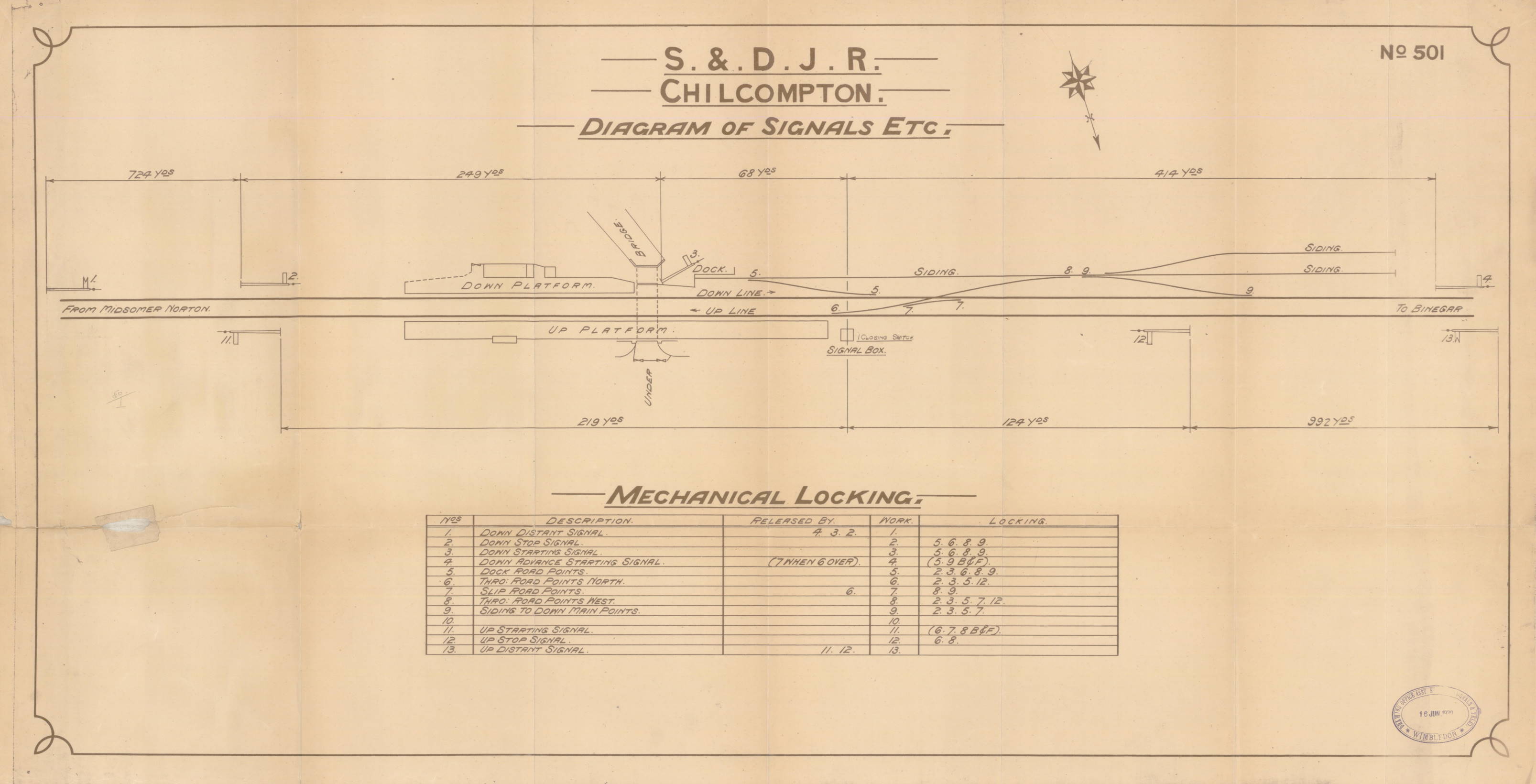
It is possible that the actual drawing style of early S&DJR signal diagrams was derived from that used by the contractors who supplied the signalling equipment, but no actual signal diagrams (as distinct from track-plans with some signalling information added to them) are known to exist for the period prior to the 1890s. By that time the diagrams were usually drawn in a style similar to that used by the London & South Western Railway (L&SWR), perhaps not surprising given that the L&SWR had responsibility for signalling on the Joint line after 1875. Unlike some other railway companies, the L&SWR adopted the practice of including the Mechanical Locking Table in the lower half of a signal diagram below the actual 'signalling layout' in the upper half; as a result L&SWR signal diagrams tended to be much deeper (often 'square-ish' in shape) than the long, narrow style used elsewhere. In later years many diagrams had an Electrical Locking Table added to them; in some older examples this might have been inserted below the Mechanical Locking Table or in a convenient corner space, but in later years the Mechanical and Electrical information was often combined in one long table. As the number of levers provided in signal-boxes became much greater then the various Locking Tables were sometimes produced as separate drawings and the actual signal diagram changed to the long, narrow style, but the only known instance of this on the S&DJR was during the 1950-60s at Templecombe Junction.
Early signal diagrams tended to provide only basic information such as the track layout with the various points and signals, each labelled with the number of the lever by which it was worked. It was not unknown for signals to have been omitted from diagrams or for there to be contradictions in the locking-tables; even in the 1960s at least one diagram hung in a S&DJR signal-box contained an error (later corrected). In later years it was the practice to state on a diagram the names of the block-posts to which the signal-box worked on either side, but in earlier years it was common simply to give an indication of the direction (eg 'to Bath', 'from Evercreech' etc) and many diagrams survived with that style for a long time. In later years also there was a practice of marking the gradient of the line at various locations on the diagram, although alternatively that information might be shown on a separate 'gradient profile' drawing displayed in the signal-box.
It was important for the signalman to know the distances of the various signals from one to the next, and from the actual SB, so the relevant distances were marked on the signal diagram. Signal distances were measured in yards, often abbreviated as 'YDS', and measured usually to the centre-line of the lever-frame. [General railway distances were measured in miles and chains (1 chain = 22 yards), but mileposts were rarely marked on signal diagrams.] In earlier L&SWR signal diagrams the 'yardage' was marked on the 'signalling layout' by linear arrows, which tended to make the diagram look a little cluttered; also the distance of more remote signals tended to be marked by reference to the next signal along, so with two or three signals in succession the signalman might have to resort to some mental arithmetic to calculate how far it actually was from the SB itself. In later years the practice changed to providing the yardage either by individual entries in the left-hand column of the locking table against the relevant lever numbers or as an horizontal 'strip' of details for all the levers placed in the middle of the diagram below the 'signalling layout' and above the locking table. The L&SWR gave the yardage for points as well as signals, whereas many other railway companies only recorded details for the actual main running signals.
With the passage of time other items of information were included on signal diagrams, partly with the growth in the amount of electrical signalling equipment in use and the need for the signalman to be aware of what was present at his location. This information included such details as the type of block-working in use and its pattern of equipment (eg tablet instrument), the numbers of the signals with electrical arm or lamp repeaters, the numbers of points equipped with electrical or mechanical detection, whether Facing Point Locks stood normally 'in' or 'out', and the identities of any track-circuits (TC) whose status was indicated in the SB. All this information was placed in a 'block' usually at the left-hand side of the diagram below the 'signalling layout' section. In most SBs the actual status of any TC was shown by an electrical indicator mounted on the instrument shelf in a similar way to arm or lamp repeaters; the only known S&DJR example of an 'illuminated' signal diagram (which showed the TC status by lights inserted in the relevant parts of the tracks marked on the diagram) was provided about 1951/52 at Templecombe Junction. That diagram was very different in style from others on the S&DJR, being much longer but narrower and it omitted the locking tables and the 'block' of additional information.
In the British Railways (BR) period after 1948 some of the ex-S&DJR SBs and GFs became the responsibility of BR (Western Region) (BR(WR)). At first many of the diagrams were modified simply by changing their title, but in due course the Western Region produced their own versions of the diagrams for many of the locations under their control and these omitted any title. Apart from the difference in style used for the actual 'signalling layout' in terms of the way in which track and signals were drawn, only the yardage for main running signals was marked. Locking tables were not included in the diagram nor any of the additional information such as method of block-working, provision of arm or lamp repeaters etc. Consequently the BR(WR) diagrams may appear a little 'spartan' compared with their predecessors and to some extent are less informative for research purposes.
| Some Examples of Different S&DJR Signal Diagram Styles | ||||||
 |
 |
 |
 |
|||
| S&DJR 1890s | S&DJR 1930s | BR(Southern Region) | BR(Western Region) | |||
| Click any thumbnail to see a larger image | ||||||
The London & South Western Railway (L&SWR) allocated a unique identification number to each SB or GF signal diagram and this practice was continued by the Southern Railway (SR). The number was shown in the top right-hand corner of the diagram and had 1, 2 or 3 digits; these numbers were known as 'roller numbers' because the master diagrams were kept on rollers in the Drawing Office. The original L&SWR list was compiled on the basis of the alphabetical order of the first letter only of the SB or GF name. When any SB or GF was abolished its number would become 'spare' and might be reallocated later to a different L&SWR/SR location. Any new SB or GF would be allocated either a 'spare' number, if any existed, or else the next number after the last one in use at the time. Although most GFs had their own discrete number, a few were given the same number as that of an adjacent SB with an 'A' suffix.
In the British Railways (BR) period some parts of the S&DJR came under the control of BR (Western Region) (BR(WR)) and various ex-S&DJR SBs and GFs became the responsibility of the Frome District of the BR(WR) Signal & Telegraph (S&T) Department. At first the S&T Department followed their Great Western Railway (GWR) predecessor's system of 'D' (Drawing) numbers and allocated new 'Dxxx' numbers to some ex-S&DJR diagrams, but in 1957 they introduced a new system of 'S' numbers [1]. Although the 'S' denoted a 'Signalling' drawing, they are often called 'stick' numbers as the 'stick' was the BR(WR) storage equivalent of the 'roller'.
The stick numbers for BR(WR) diagrams had the format 'Sxxx/yy', where 'xxx' was the 'registered number' (1 to 4 digits long) for the SB or GF allocated in geographical order along the line and '../yy' defined the actual type of drawing (for example Sxxx/12 would be the signal diagram). (Most ex-S&DJR locations were given a 3-digit 'S' number, but a few of the later acquisitions had a 4-digit number.) At first BR(WR) simply applied 'D' or later 'S' numbers to existing diagrams in the bottom right-hand corner and crossed out the former SR 'roller' number, but in later years any new diagrams had just the 'S' number'. Unlike the original 'roller' numbers, the 'D' or 'S' numbers were placed in the outer margin of the master drawing and therefore were not visible when the diagram was displayed in a frame in the SB or GF.
Click here to see a list of all known 'Roller', 'Drawing' and 'Stick' numbers for S&DJR signal diagrams.
| Diagram Sources and Publications | |||||||
|
Primary Sources. There are a number of primary sources for S&DJR signal diagrams, which include:-
Note: A word of caution is necessary with regard to the provenance of 'official' records. It was not unknown for 'office copies' of signal diagrams to be used as 'working documents' for the purpose of planning a proposed alteration which in fact was never implemented. Although one might expect such draft versions to be destroyed when no longer required, there are examples which have survived and passed eventually into private hands; without supporting knowledge of their background, there is a risk that they have been used erroneously as 'factual evidence' of something which never existed in practice.
Some signal diagrams printed in railway-related publications may have been 'reconstructed' from unconfirmed evidence, in order that a reasonable indication could be given of the signalling at a particular S&DJR location, and therefore may include items which actually had not existed concurrently. Similarly it is unfortunate that some authors have made inaccurate comments as a result of attempts to reconcile diagrams, plans and photographs from different periods without understanding the background to any apparent inconsistencies.
WCRA Collection. Some copies of S&DJR signal diagrams are held in the West Country Railway Archives collection, having been gathered from a variety of sources during many decades of research, and some of them can be found in the relevant RailWest pages. The author has produced his own outline diagrams for most S&DJR locations (in many cases for more than one date) and some of these can be seen also in the relevant RailWest pages; a few are listed in the RailWest Diagrams Index, but that Index is not yet complete. In some cases the diagrams have been compiled from incomplete information and it has been necessary to make some assumptions based on circumstantial evidence, so the author does not wish to publish such diagrams in RailWest without suitable supporting comments to ensure that they are not regarded as definitive by mistake. It should be noted that there are various places in RailWest where, in the absence of definitive evidence, a 'reasoned opinion' had been provided in order to provide a better understanding of a signalling installation, but hopefully all such instances have been highlighted as being distinct from actual fact.
Signalling Record Society. The Signalling Record Society (SRS) has produced signal diagrams for most S&DJR locations and copies of these can be purchased from their Drawing Office; however it should be noted that these are essentially 'outline diagrams' and not full-sized reproductions of original SB diagrams. Most of the SRS's S&DJR diagrams originated from the work of the late George Pryer (a SRS founder member), but they are not annotated with any of the supplementary information which is contained in Pryer's own versions, nor have many of them been updated yet to take account of any amendments identified as a result of the work for the revised edition of Pryer Volume 3 (see below). Some SRS drawings have been reproduced in various other publications about the S&DJR, but given the age of such publications it might be prudent to compare any such drawings with the revised edition of Pryer Volume 3.
Pryer Volume 3. The late George Pryer published a series of books of GWR and SR Signal Box Diagrams (using his own outline drawings) and Volume 3 covered the S&DJR. Correspondence with him during its preparation led to a useful exchange of information, some of which was incorporated into the WCRA collection at that time. In the years since the publication of Volume 3 (and the untimely death of its author) ongoing research has yielded additional information to augment the original material, but also identified some errors. In 2018 the Signalling Record Society published a Revised Edition of Volume 3 [2] (obtainable here); this retained the original format as far as possible, but with alterations to various details in many of the diagrams and the addition of an extensive Addenda & Corrigenda section. Despite best efforts to ensure that the revised edition was as accurate as possible, it is clear that a few errors crept into that revision and these are being recorded in a separate Errata List as and when they are identified; click here to see the latest Version of that list held in RailWest.
Judge & Potts. In 1979 the Oxford Publishing Company (OPC) published "An Historical Survey of the Somerset & Dorset Railway" by CW Judge and CR Potts [3], a book often referred to colloquially simply as 'Judge & Potts'. This covered almost all S&DJR locations with a collection of photos, maps and signal diagrams for each site. However it should be noted that in many instances the material provided for a location related to a variety of different dates, which can cause confusion for the unwary reader who may try to compare (say) an early map with a later photograph without knowledge of some intervening alterations. Most of the signal diagrams came from the Signalling Record Society, so the cautionary comments above about the SRS collection should be noted.
Irwell Press. In 2021 the Irwell Press published "The Somerset & Dorset Railway - Bath to Bournemouth" by Derek Phillips [4]. This book was in a similar format to the Judge & Potts book described above, but with many more photographs and expanded captions. Sadly from a signalling perspective it used the same out-of-date set of SRS signalling diagrams as were used in the earlier OPC book and therefore the cautionary comments above about the SRS collection should be noted. It is unfortunate also that some photo captions repeat errors previously written about the same photographs in other publications.
Pictorial Atlas. In 2023 the Lightmoor Press published "A Pictorial Atlas of the Somerset & Dorset Joint Railway" by Richard Harman and Neil Parkhouse [5] as a 2-volume boxed set. This is similar to the Irwell Press book described above, but with some key differences. Firstly the photographic coverage concentrates mainly on early pre-Grouping black-and-white (B&W) views and colour images from the British Railways era, rather than the B&W views of the 1950s and 1960s more commonly used in other publications. Secondly the signalling diagrams have been derived from the revised 2018 edition of Pryer Volume 3 (described above) and have been redrawn by the author to provide a consistent match with the orientation of the accompanying scale plans, although a few errors have crept in during that process - almost inevitable in a work of this magnitude.
Finally...
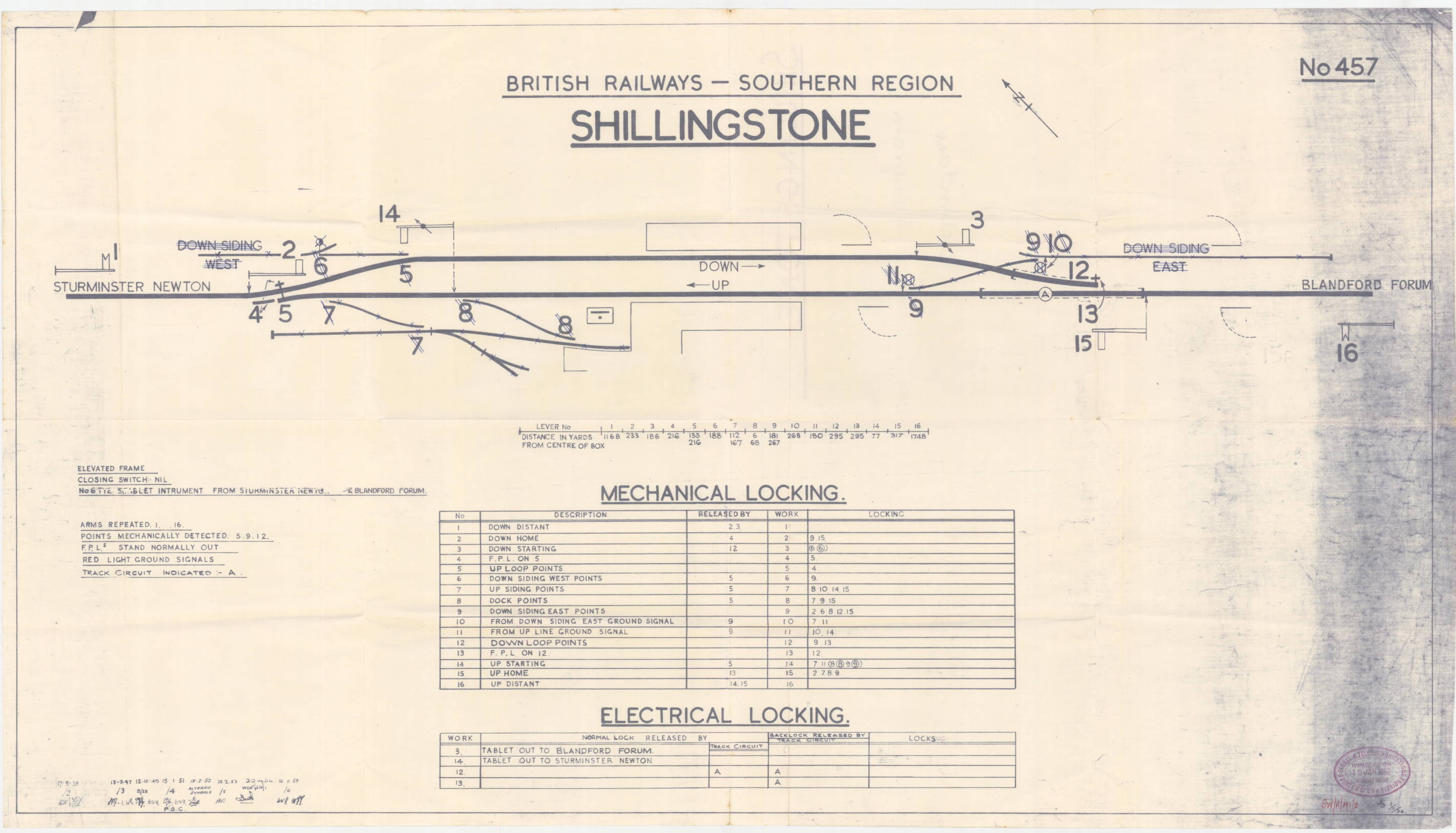
...surviving diagrams! The image at the head of this page shows the framed BR(WR) signal diagram which was removed from the SB at Glastonbury in 1966 and is now in the Museum of the Somerset & Dorset Railway Heritage Trust at Midsomer Norton South station. It is known that the framed diagram from Shillingstone SB also passed into private hands and it was found that fortuitously an earlier BR(SR) diagram survived behind the later diagram for the final rationalised layout of 1966. The framed BR(SR) diagram from Cole appeared at an auction in 2022 (click here to see a photo). A small number of unframed coloured diagrams are known to exist which may have been removed from a SB frame at some date or perhaps were simply permanent copies to be kept in the SBs in case of need. Given the popularity of the former S&DJR, and the number of framed signal diagrams from other railways which occasionally appear at auctions, it would be nice to think that there are more survivors somewhere - details and photographs always welcome!
© CJL Osment 2021-23
Acknowledgements to
the Signalling Record Society
and the late Peter Cattermole for archive material.
Glastonbury diagram photograph © David Milton, all other images WCRA collection.
References
|
© West Country Railway Archives 2021 Page last updated: 05 March 2024 |
URL:
E-Mail: |
||||||


