


 |
Lynton and
Barnstaple Railway The Signal Boxes and Ground Frames |
|
| Introduction | Signal Boxes | Lever Frames | Description Plates | Ground Frames | Signal Diagrams |
This page describes the Signal-Boxes and Ground-Frames of the former Lynton and Barnstaple Railway (L&BR), including some items of their equipment such as the lever-frames. Please see the separate Introduction to L&BR Signalling page for general background information and details of other pages on RailWest about the signalling of the L&BR. Click here for more general historical details about the L&BR and a Bibliography.
The firm of Evans O'Donnell (EoD) of Chippenham was chosen as the signalling contractor for the L&BR and so all the original signalling installations reflected the practice of that company. However after the takeover of the line by the Southern Railway (SR) in 1923 some different equipment did appear as a result of minor alterations and general maintenance. Evans O'Donnell erected signal-boxes at the two terminal stations of Barnstaple and Lynton, at the intermediate passing-loops at Chelfham, Bratton Fleming, Blackmoor and Woody Bay stations, and also at the passing-loop adjacent to the L&BR's locomotive and carriage works at Pilton.

A simulation of the lever description plates in Chelfham
signal-box
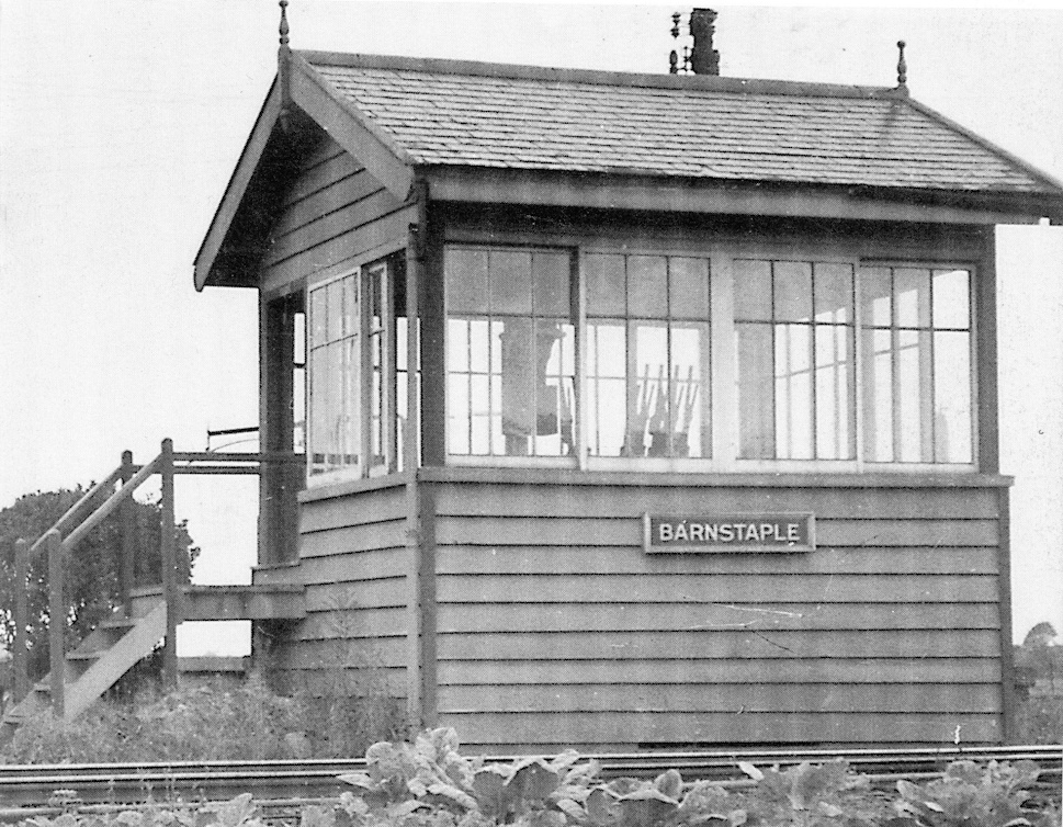 At Barnstaple and Pilton there
were elevated signal-boxes (SB) of a roughly identical EoD design and the
picture shows the SB at Barnstaple in 1935 (click for larger image). There is some evidence
to suggest that it had been intended for that SB to have a timber
superstructure on a stone base, but in fact the SB was built as an all-timber
construction. Somewhat unusually the upper part of the structure was fully
glazed on all four sides, which may have made it rather uncomfortable for the
signalman on a hot sunny day! In contrast, it appears that the SB at
Pilton was constructed originally as a timber superstructure on a tall masonry base, which
subsequently was reduced to little more than a low plinth (possibly circa-1918).
Both SBs were equipped with a 9-lever EoD interlocking frame, mounted
directly on the operating floor near the front of the box and supported by two large transverse joists;
a trap-door in the floor near to the rear wall gave access to the 'void' under the floor. The two SBs at Barnstaple and Pilton were the only
'elevated' SBs to have existed on the L&BR, all other locations using the 'huts'
described below. At both locations the single-line Electric Train Tablet (ETT) instruments were housed in the SBs, which probably were manned throughout
the day by their duty signalmen.
At Barnstaple and Pilton there
were elevated signal-boxes (SB) of a roughly identical EoD design and the
picture shows the SB at Barnstaple in 1935 (click for larger image). There is some evidence
to suggest that it had been intended for that SB to have a timber
superstructure on a stone base, but in fact the SB was built as an all-timber
construction. Somewhat unusually the upper part of the structure was fully
glazed on all four sides, which may have made it rather uncomfortable for the
signalman on a hot sunny day! In contrast, it appears that the SB at
Pilton was constructed originally as a timber superstructure on a tall masonry base, which
subsequently was reduced to little more than a low plinth (possibly circa-1918).
Both SBs were equipped with a 9-lever EoD interlocking frame, mounted
directly on the operating floor near the front of the box and supported by two large transverse joists;
a trap-door in the floor near to the rear wall gave access to the 'void' under the floor. The two SBs at Barnstaple and Pilton were the only
'elevated' SBs to have existed on the L&BR, all other locations using the 'huts'
described below. At both locations the single-line Electric Train Tablet (ETT) instruments were housed in the SBs, which probably were manned throughout
the day by their duty signalmen.
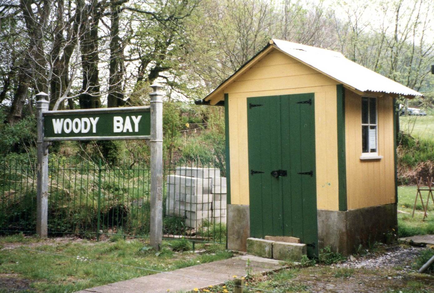 At the other
locations only small platform-level wooden huts of identical
design were provided as SBs and this picture (click for larger image) shows the
former Woody Bay SB (after restoration in 1999); this SB was recorded in the
1935 Sale Catalogue as measuring 6’x5’x7’. (Note the concrete plinth which had
been added at some date, probably as a result of timber rot.) In each hut the entrance was
a double-door in the front wall, with a 7-lever EoD interlocking frame mounted ‘back-to-track’ against the rear
wall. At these stations the ETT instruments were kept in the booking-office;
apart from the small size of the 'hut' SBs, this arrangement probably reflected the fact that these SBs were not manned
permanently, but merely visited as required by the stationmaster or
porter who also acted as signalman. All the original huts were mounted on
station platforms, but at an early date (circa-1900?) the hut at
Lynton was relocated to a ground-level site at the station throat. In 1924 (to be confirmed) it was replaced by a ground-level pent-roof hut of L&SWR/SR design
in the same location; this hut was recorded in the 1935 Sale Catalogue as measuring 9'x8'x7'6" (average).
At the other
locations only small platform-level wooden huts of identical
design were provided as SBs and this picture (click for larger image) shows the
former Woody Bay SB (after restoration in 1999); this SB was recorded in the
1935 Sale Catalogue as measuring 6’x5’x7’. (Note the concrete plinth which had
been added at some date, probably as a result of timber rot.) In each hut the entrance was
a double-door in the front wall, with a 7-lever EoD interlocking frame mounted ‘back-to-track’ against the rear
wall. At these stations the ETT instruments were kept in the booking-office;
apart from the small size of the 'hut' SBs, this arrangement probably reflected the fact that these SBs were not manned
permanently, but merely visited as required by the stationmaster or
porter who also acted as signalman. All the original huts were mounted on
station platforms, but at an early date (circa-1900?) the hut at
Lynton was relocated to a ground-level site at the station throat. In 1924 (to be confirmed) it was replaced by a ground-level pent-roof hut of L&SWR/SR design
in the same location; this hut was recorded in the 1935 Sale Catalogue as measuring 9'x8'x7'6" (average).
Note: It is not known if the original 'huts' were of EoD or local design. During restoration work on the surviving hut at Chelfham a section of timber panelling was removed for replacement and on the inside was found an inscription in pencil which read "Thomas Marshall Crang January 1st 1898". Apparently TM Crang was a carpenter & joiner who was born in Barnstaple in 1875. This artefact (L&BR Museum reference LYNBR:2025.0015) is now on show at Chelfham station - click here to view.
Nameboards. In SR days wooden nameboards were fixed to the various SBs. Those at Barnstaple Town and Pilton were placed on the front wall below the window sill, while the EoD huts had them fixed on the front gable end above the door. On the replacement SR hut at Lynton the nameboard was placed on the front wall above the window. Given the apparent absence of nameboards in earlier photographs, it would seem likely that they were a new provision by the SR.
After Closure. In total the L&BR had two 'elevated' SBs, five platform-level 'huts' and one replacement SR-era hut. Two of the original huts survive:- the one at Woody Bay has been restored and is in operational use by the Lynton & Barnstaple Railway Trust (L&BRT), whilst the one at Chelfham has been restored also but is not yet in operational use. What is believed to have been the 'hut' from Blackmoor was moved to a location beside the trackbed some distance north of that station, where it was used for farm storage; it was photographed there in 1967 in a dilapidated condition and no longer exists (probably burnt as firewood). The hut from Bratton Fleming was moved to the well which supplied the station water tank when an electric pump was installed to supply the nearby Quarry House; sadly some years later a tree fell on it during some clearance work and it was sold off as a pile of firewood! The former 'elevated' Barnstaple SB survived for many years in private ownership elsewhere, but it was returned to the L&BRT in 2023 and is now (2025) undergoing extensive restoration with a view to becoming a future 'museum exhibit'. The fates of the superstructure from Pilton SB, the original 'hut' at Lynton and its SR-era replacement are not recorded.
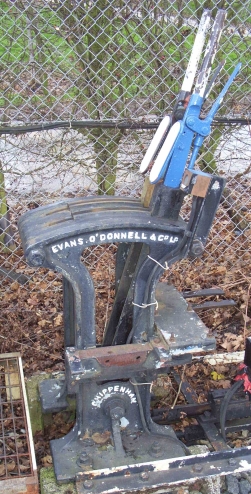 It is known from photographic evidence that the smaller 'hut' signal-boxes
were equipped with Evans O'Donnell lever-frames of a type designed for use at ground level.
The photograph (click for larger image), although not of an ex-L&BR
item, shows a typical example of a small EoD ground-level frame with 2 levers, with
the tappet interlocking mounted about half-way up the rear of the frame. (Such frames are often called 'knee' frames, on the basis that the main
framework came up to about knee height.) The same type of frame was used also
for the various original ground-frames (GF) installed on the line.
It is known from photographic evidence that the smaller 'hut' signal-boxes
were equipped with Evans O'Donnell lever-frames of a type designed for use at ground level.
The photograph (click for larger image), although not of an ex-L&BR
item, shows a typical example of a small EoD ground-level frame with 2 levers, with
the tappet interlocking mounted about half-way up the rear of the frame. (Such frames are often called 'knee' frames, on the basis that the main
framework came up to about knee height.) The same type of frame was used also
for the various original ground-frames (GF) installed on the line.
It is evident from some surviving 1898 plans that the same pattern of ground-level lever-frame was installed in the elevated SBs at Barnstaple Town and Pilton, the frames being mounted directly onto the operating floor supported by large transverse joists. (It is possible that this arrangement was used instead of a more conventional 'elevated' type of lever-frame simply for equipment consistency.) One key difference was that the lever-frames in the ground-level 'huts' had straight lever tails, which provided a horizontal drive to the point rodding, whereas in the two elevated SBs the levers had right-angled tails to provide a vertical drive down (presumably) to pedestal cranks sited at ground-level.
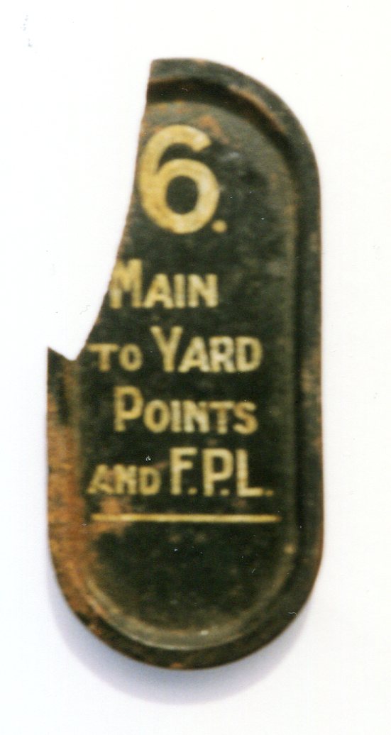 In
SR days at least, each lever carried an oval metal description plate, on
which was sign-written the number of the lever, its function and (where
relevant) the number(s) of any other lever(s) which had to be pulled first in order to release
that lever. It is probable that EoD fitted their own description plates
to the initial installations (a common practice with signalling contractors),
but the style of those is unknown, nor is it known if the SR replaced any plates in later years. The photograph (click for larger image) shows a damaged
example believed to have come from Pilton SB; this
measures approximately 5½"x2½".
Although the style is similar to, but smaller than, that used by the SR, it is probable that the SR
design was derived from one of their contractors (which had included EoD), so currently it is not possible to determine whether or not the design of
L&BR lever description plates was altered at any time. It was SR practice to
paint each plate in the same colour as its lever (in this example black for
points), but again it is not known if any original EoD plates followed the same
convention.
In
SR days at least, each lever carried an oval metal description plate, on
which was sign-written the number of the lever, its function and (where
relevant) the number(s) of any other lever(s) which had to be pulled first in order to release
that lever. It is probable that EoD fitted their own description plates
to the initial installations (a common practice with signalling contractors),
but the style of those is unknown, nor is it known if the SR replaced any plates in later years. The photograph (click for larger image) shows a damaged
example believed to have come from Pilton SB; this
measures approximately 5½"x2½".
Although the style is similar to, but smaller than, that used by the SR, it is probable that the SR
design was derived from one of their contractors (which had included EoD), so currently it is not possible to determine whether or not the design of
L&BR lever description plates was altered at any time. It was SR practice to
paint each plate in the same colour as its lever (in this example black for
points), but again it is not known if any original EoD plates followed the same
convention.
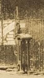 As well as the various SBs a small number of uncovered ground-frames
(GF) existed on the railway. A GF was located at the Lynton end of Pilton yard and worked the points for the exit from the yard at that end; this
GF was unlocked by the tablet for the section to Chelfham. At Blackmoor a new Down Siding
was installed shortly after the line was opened and this was worked by an adjacent GF, shown in the picture
here which is a hazy enlargement from a distant
view; this GF may have been unlocked by a key from the main SB lever-frame, but
records are conflicting and it is listed in SR days as being released by tablet. Each of those GFs contained just a single lever and was of the same EoD
pattern as the lever-frames used in the smaller 'hut' SBs.
As well as the various SBs a small number of uncovered ground-frames
(GF) existed on the railway. A GF was located at the Lynton end of Pilton yard and worked the points for the exit from the yard at that end; this
GF was unlocked by the tablet for the section to Chelfham. At Blackmoor a new Down Siding
was installed shortly after the line was opened and this was worked by an adjacent GF, shown in the picture
here which is a hazy enlargement from a distant
view; this GF may have been unlocked by a key from the main SB lever-frame, but
records are conflicting and it is listed in SR days as being released by tablet. Each of those GFs contained just a single lever and was of the same EoD
pattern as the lever-frames used in the smaller 'hut' SBs.
Between the two level-crossings at Pilton there was a siding to serve a wharf on the River Yeo and this was also worked by a local GF. The original GF was of the same EoD design as other GFs and appears from photographic evidence to have been just a single lever. However there are no known photographs of the GF which existed in later years after the siding was altered, so it is unclear if the original EoD GF was reused or a replacement GF was provided, possibly of a different size and pattern. In SR days the GF was unlocked by the tablet for the section to Barnstaple Town and it is probable that the same arrangement was used for the original GF. Sadly it is unclear from the limited photographic coverage of the EoD GFs whether their levers were fitted with lever description plates in the same manner as the SB lever-frames.
A 3-lever GF was installed at Bratton Fleming in 1932; this was a 'knee' frame of the Stevens & Sons pattern widely used by the SR (usually with levers at 4.5/8" spacing) and different in appearance from an EoD frame. The levers were fitted with lever description plates of the contemporary SR pattern.
No details are known of the actual pattern of tablet locks fitted to the various GFs nor how they were arranged to interact with the levers, although in the case of the 1932 Bratton Fleming GF a photograph suggests that its lock was attached to the upper part of its release lever.
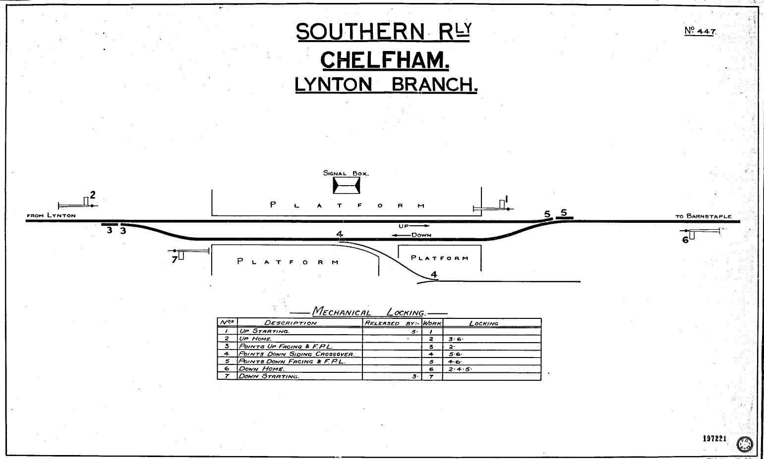
In Southern Railway days at least there would have been a signal diagram hung in each SB, showing the layout and numbering of the signals and points worked from its lever-frame. (Although equivalent diagrams may have existed for the GFs as a record for the signal engineer, it would seem unlikely that any copies were displayed at the actual GFs given the simplicity of those installations.) Only one known SR signal diagram copy exists (No 447 for Chelfham), which appears to have been drawn new by the SR in 1923 in a style derived from earlier London & South Western Railway (L&SWR) practice. Although at least one 'office copy' diagram (Bratton) is known to exist from early L&BR days, the author is not aware of any evidence that signal diagrams were actually displayed in the SBs at that time, although it would seem a likely practice, in which case they may have been supplied by Evans O'Donnell as part of their 1898 installation.
 |
The SR allocated each SB or GF a 'roller number' (so called because the master diagrams were kept on rollers in the drawing office) and the known numbers for L&BR diagrams were as follows:- |
|||||||||||||||||||
|
||||||||||||||||||||
The apparently random allocation of numbers was due simply to the fact that the SR allocated some 'spare' numbers from an existing list. (Some of the numbers had been used elsewhere previously and most of them were used again elsewhere after closure of the L&BR.) It will be noted that, although a number was allocated for the GF at Barnstaple Quay (Pilton), no number is listed for the GF at the Lynton end of Pilton Yard. This may be simply a gap in the surviving records, or an oversight, or perhaps that GF was recorded under the same number as Pilton SB.
Note: the terminology used on the Chelfham diagram to describe the functions of the various point levers, although not unknown elsewhere on the SR, appears not to match either earlier L&SWR practice or later SR practice. Confusingly it does not match the descriptions on the actual point lever plates as photographed at Chelfham, which are assumed to have been the original EoD items. One can only assume that the SR draughtsman was working simply with evolving contemporary practice rather than by reference to any pre-existing L&BR records.
© CJL Osment 2018-25
Acknowledgements to Michael Bishop, David Moore and the Signalling Record Society
for archive information.
EoD GF photograph courtesy Nick Wellington, No 6 plate photograph courtesy David Hudson, Chelfham lever descriptions
image courtesy of John Hinson, Crang inscription photograph courtesy Graham Lee,
all other images WCRA Collection.
| Interested in
the Lynton & Barnstaple Railway? Then why not join the Lynton & Barnstaple Railway Trust and help to re-build England's premier narrow-gauge line? |
| Introduction | Signal Boxes | Lever Frames | Description Plates | Ground Frames | Signal Diagrams |
|
© West Country Railway Archives 2018 Page last updated: 13 July 2025 |
URL:
E-Mail: |
||||||


