 |
Somerset &
Dorset Joint Railway Signalling at Midford |
|
||||||||
|
||||||||||
|
||||||||||
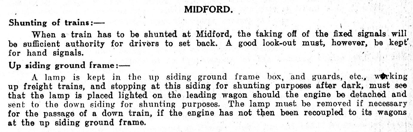
The railway station and signal-box at Midford were situated on the main line of the Somerset & Dorset Joint Railway (S&DJR), on the section from Bath Junction to Evercreech Junction in the county of Somerset which was known historically as the 'Bath Extension'.
 |
 |
|
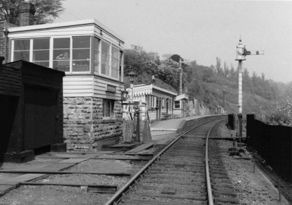
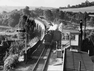
| Midford looking up the line through the station and down the line across the viaduct | ||
In 1874 the Somerset and Dorset Railway (S&DR) opened its 'Bath Extension' from Evercreech Junction to Bath and a station was provided at Midford. At first the line was single-track throughout with a few passing-places and, according to an undertaking given to the Board of Trade (BoT) by the S&DR on 15-July-1874, the only block post between Bath Junction and Radstock was at Wellow (the next station south of Midford). The S&DR became the S&DJR in 1875 when the line was leased jointly by the Midland Railway (MR) and London & South Western Railway (L&SWR). Click here to read more about early S&DR/S&DJR Signalling and the nature of the original signalling and layout arrangements on the Bath Extension.
With a steady increase in traffic various sections of the Bath Extension were doubled piecemeal, until by 1894 the entire line had been doubled northwards from Templecombe No.2 Junction up to Midford. The last section from Midford into Bath was to become one at the bottle-necks of the S&DJR system, for all Down trains leaving Bath were faced with an immediate climb at 1 in 50 and 1 in 66 for over two miles through Devonshire Tunnel (440 yards) to the north end of Combe Down Tunnel (1829 yards) - both tunnels had limited clearance and were very unpleasant to work through (Combe Down being the longest unventilated tunnel in Britain). It was the cost of doubling these tunnels that finally prevented completion of the doubling right through to Bath and although some work was done in preparation for doubling up as far as the south end of Combe Down Tunnel, the scheme was never carried out. This left Midford as a key location at the change from single to double track.
Midford station was a simple affair, a single platform with wooden buildings set on the Up side of the line at a location where it ran on a ledge along the hillside. Northwards the line passed under a minor road by bridge No 17, known as the 'Long Arch' - it was built at such a skew that, at 37 yards, it was more like a short tunnel. Immediately north of bridge 17 a point, facing to Up trains, led to the two sidings on the Down side which formed the diminutive goods yard. South of the station the line went immediately onto a double track viaduct which carried it across the main road, a river, the Great Western Railway's Limpley Stoke - Camerton branch and the remains of the Somerset Coal Canal, before passing through a cutting and winding its way on to Radstock. In the cutting a siding trailed off the Up line; although little used in later years, at one time it saw traffic such as hay shipped out from local farms and explosives unloaded for local collieries.
After the Grouping of the railways of Great Britain in 1923 the S&DJR became a Joint line under the control of the London, Midland & Scottish Railway (LMS) and the Southern Railway (SR), who were the successors to the MR and L&SWR respectively. When the railways were nationalised in 1948 the Joint line came under the control of British Railways (Southern Region) (BR(SR)), but in due course control of the old Bath Extension section passed to British Railways (Western Region) (BR(WR)) until the line closed on 6th March 1966.
When the Bath Extension was opened the block working on the single-line was by block telegraph without any train staff, and under the terms of the S&DR's 1874 undertaking to the BoT the first block post south of Bath was supposed to be at Wellow. However it is clear from the evidence in the BoT Report on the disaster at Foxcote (near Radstock) in August 1876 that Midford station had been acting as some form of intermediate block post at that time. It is unclear exactly what the original signalling arrangements were at Midford, but it would appear to have included the provision of Distant and Home signals in both directions, worked from a lever-frame probably located in a small wooden hut somewhere on or close to the platform. Even after the Foxcote accident it is clear that this installation continued to function as a block post, as evidenced by references in the S&DJR's Working Timetable Appendix No 7 dated 1-March-1886.
On 3-October-1886 Electric Train Tablet (ETT) working was introduced between Bath and Radstock (using Tyers No 1 instruments), after which Midford became a non-block location within the Bath Single Line Junction - Wellow section. Nevertheless it appears that the signals remained in use at Midford for 'station stop' purposes only. The steep gradient out of Bath necessitated the provision of banking engines on almost all Down freight trains, but assistance was needed only as far as the summit at the north end of Combe Down Tunnel. Special banking arrangements had been in force since 1876 on the Bath Single Line Junction - Midford section involving the use of a 'Bath Bank Staff' and these continued with the advent of ETT working (click here for further details).
In 1892 the line from Midford to Wellow was doubled and new signal-boxes (SB) were provided at both locations, the new work being opened on 28th August. Midford now became a block-post again and worked ETT to Bath Single Line Junction (presumably using the Tyers No 1 instrument relocated from Wellow) and Absolute Block to Wellow using S&DJR 'block telegraph' instruments. The 'Bath Bank Staff' arrangements continued, but with the bank engine staff now being interlocked with the ETT instrument at Bath Single Line Junction SB.
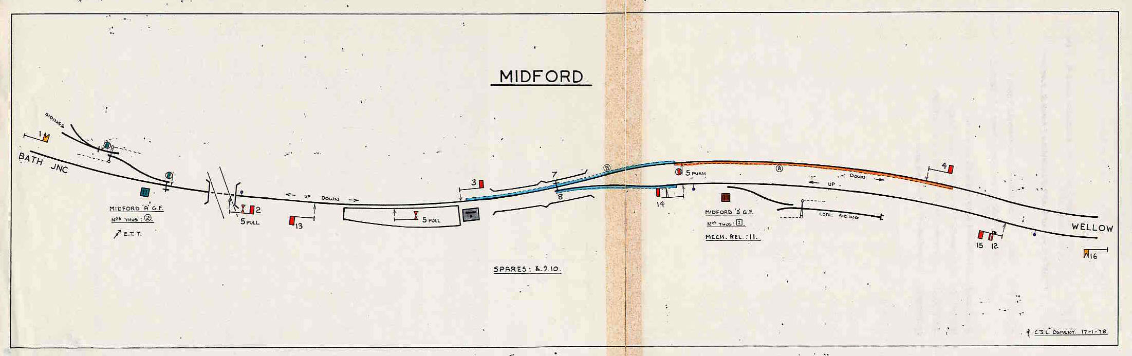
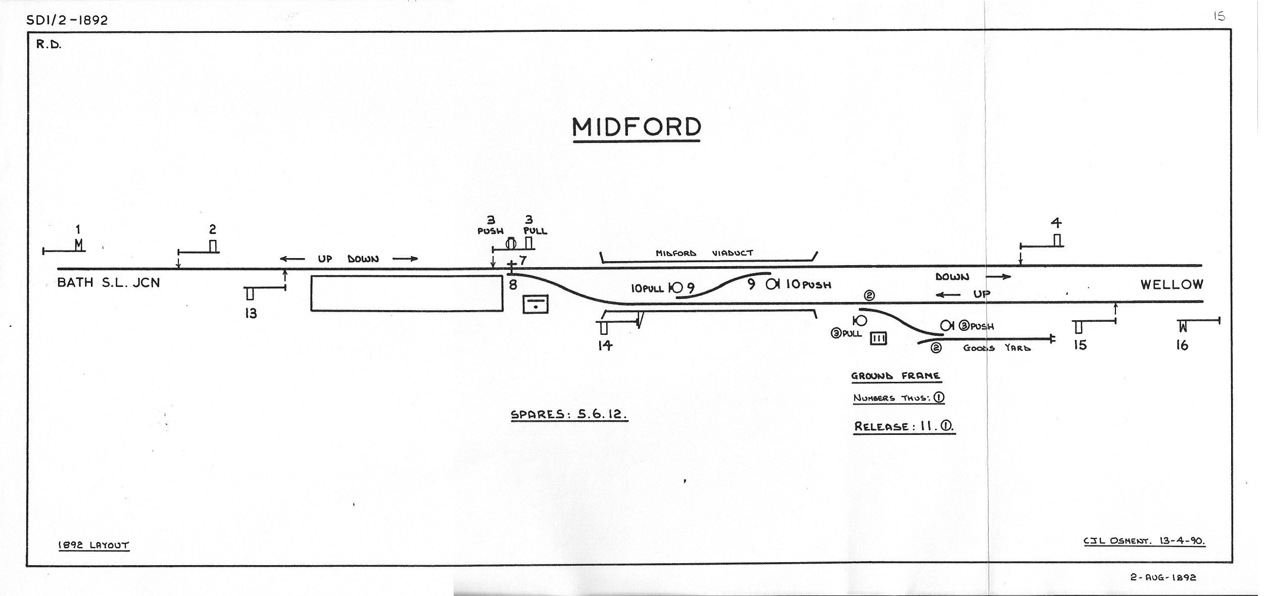
The new SB at Midford was situated on the Up side of the line between the end of the platform and the viaduct, and it was built to the same S&DJR TYPE 2 style as other replacement SBs on the Bath Extension - stone with a timber superstructure decorated with a distinctive style of wavy valencing. The new double track extended right across the viaduct, with a crossover (points 9) about half way along, and the Up Inner Home signal (14) was on a wooden post bolted onto the outside of the viaduct. One feature of the early signalling at many S&DJR double-line locations was the provision of a subsidiary arm under the stop signal next in rear of the section signal; in common with other S&DJR subsidiary arms, this would have been a full-size arm with a ring and here at Midford signal 3PUSH was an example. Lever 3 was a 'push-pull' lever, which normally stood in the mid-stroke position; the signalman could pull the lever back to operate one signal, or push the lever forward to operate a different signal.
 |
 |
|
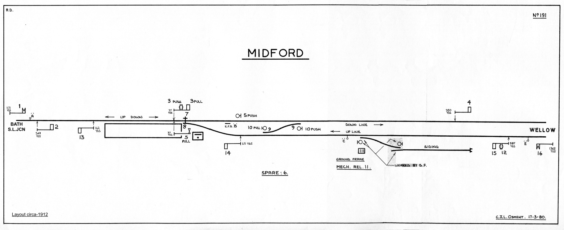
| Midford Signal Diagram 1892 | Midford Signal Diagram circa-1912 | |
| Click diagram for larger image | Click diagram for larger image |
It is believed that all the original main running signals provided in 1892 were lower-quadrant (LQ) arms on wooden posts. At some date circa-1900 three additions were made to the signalling at Midford (see the circa-1912 diagram above). Lever 12 was brought into use to control a subsidiary ringed arm located beneath the Up Outer Home (15), although its function is a little confusing; described as a 'Shunt By' arm in the lever-frame locking table, it was often referenced in notices as a 'Calling On' arm and in BR days it was marked on SB diagrams as a 'Warning' arm. In later years it seems to have been used to draw trains forward to shunt the Up Siding, either to put a light engine out of the way or to drop off a vehicle with a hot-box. As it locked signals 2 and 3 it could not be used for such moves when a Down train had been signalled.
Lever 5 was brought into use (probably at the same time) as a 'push-pull' lever. The 5PUSH function operated a new ground signal, which was located on the outside of the Down line just south of the facing points 8 and controlled movements from the Down line back onto the single-line. The 5PULL function worked what was perhaps the most notable feature of the installation at Midford, namely the 'wrong-road' signal situated on the platform. This was probably the first signal at Midford to be installed on a lattice metal post rather than a wooden post. Eventually there were two such signals at Midford, as on 11-June-1929 (S&DJR Signal Instruction 293) a second 'repeater' arm for 5PULL was provided under the Down Home 2 (which in fact stood on top of the Long Arch overbridge). These signals were used on the occasions when an Up Goods failed to make the climb up the 1-in-50/1-in-100 gradient to Combe Down tunnel. The driver would telephone back to Midford (using a telephone provided for that purpose close to the southern end of Combe Down tunnel) and receive the signalman's permission to reverse back out of the section. On return to Midford the train might be shunted on to the Down line, but some times the traffic pattern demanded that it be put on to the Up line while it awaited an assisting engine or tried to build up a good head of steam; it was for these moves onto the Up line that signal 5PULL was used.
In the original 1892 layout the only provision for goods traffic was a single siding trailing off the Up line south of the viaduct. This siding was controlled by a ground-frame (GF), housed in a small wooden hut and bolt-locked by lever 11 in the signal-box. However in December 1894 a small goods yard with two sidings was opened to the north of the station. This yard was situated on the Down side of the line immediately on the Bath side of the 'Long Arch' overbridge and was accessed by a point in the single-line facing to Up trains. This connection was controlled by its own GF, situated in a small wooden hut on the Up side of the line, and locked by the single-line tablet. This new GF became known as GF 'A', while the original one at the Up Siding became GF 'B'. Because GF 'A' was not controlled directly from the SB (unlike GF 'B') the goods yard and GF 'A' never appeared on the actual SB diagram. Both GFs also worked ground signals controlling movements into and out of their respective sidings.
The crossover (points 9) on the viaduct would seem to have been of little use and eventually was removed (together with the associated ground signals 10PUSH and 10PULL), this alteration being authorised by a S&DJR Officer's Minute dated April 1918. As part of a general programme to improve speed restrictions on the line, on 9-April-1933 the facing points (8) were re-sited much further south along the viaduct, thereby raising the speed restriction for Up trains from 20 mph to 40 mph. The relocated points were now 98 yards south of the signal-box, with ground signal 5PUSH being relocated between the Up and Down lines 206 yards from the SB (S&DJR Signal Instruction 330). This alteration also involved a further southwards relocation of the Up Inner Home bracket signal (14) to a position 206 yards from the SB, and the Down Advanced Starting signal (4) to 470 yards, both the changes taking place the previous weekend on 2-April-1933.
After 1933 there were no further changes to the general layout at Midford until about 1959/60, when the Up Siding and GF 'B' were taken out of use. BR records are confusing here, as it was stated in June 1959 that these had been taken out of use, yet again in 1960 it was listed that they "will be taken out of use" on 28th February that year. The goods yard and GF 'A' were closed in 1963/64 and recovered on 29-June-1964.
| Various S&DJR WTT Appendix instructions for Midford | ||||
 |
 |
 |
||
| 1905 Edition | 1914 Edition | 1933 Edition | ||
| Click thumbnails for larger images | ||||
Signal 3PUSH was abolished on 15-April-1913 (S&DJR Signal Instruction 237), after which lever 3 reverting to 'normal' working of the Down Starting signal only. By 1922 the original Up Inner Home (14) had been replaced by a right-hand lattice bracket sited just south of the viaduct. This signal was relocated again further southwards to a position 206 yards from the SB as part of the 1933 layout alterations, and the Down Advanced Starting (4) was moved out also to 470 yards, both these changes taking place on 2-April-1933 (S&DJR Signal Instruction 330). At the same time ground signal 5PUSH was relocated between the Up and Down lines 206 yards from the SB. Then on 21-May-1933 both ground signals at GF 'B' were removed (S&DJR Signal Instruction 336).
The Up Distant signal (16) was lowered by 12' on 2-September-1924 and two days later the Down Distant signal (1) was lowered by 6' (both S&DJR Signal Instruction 276). On 29-July-1936 the Down Starting signal (3) was demolished as a result of an accident with a runaway train, but evidence would suggest that the original post was re-erected in a shortened form. It is probable that it was at that time that the signal was fitted with an upper-quadrant (UQ) arm and this may have been the first UQ arm to be provided at Midford; it is presumed that all subsequent signal replacements done at Midford also used UQ arms. The Down Distant was replaced by a new signal 15' high on 22-March-1942 and also on the same date a 25' high replacement was provided for the Up Starting (13) (both S&DJR Signal Instruction 389).
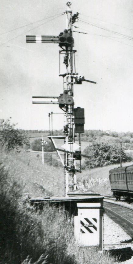 Further signal
alterations took place on 25-July-1948, when the Up Outer Home signal 15
and subsidiary 'Shunt By' arm 12 were replaced by new signals on a new
20' post 81 yards further away from the SB (see picture). Signal 12 was provided in a
new form, becoming a small horizontally-striped arm with an adjacent
indicator box on the signal
post, and was described now as a 'Warning' signal. [Note also in the picture the 'Rule 55 exempt' white
diamond sign, with the large black 'T' on its face to denote that a telephone to the
signal-box was provided in the white cabinet with the black-and-white
striped plate in the foreground.] On the same day the Up Distant signal was replaced by a new signal
12' high located 306 yards further away from the SB and now 1000
yards away from the re-located Up Outer Home. Subsequently however
signal 12 was removed altogether on 28-February-1960 with the closure of the Up Siding
(at which time it was still described as a 'Calling On' arm in the abolition
notice).
Further signal
alterations took place on 25-July-1948, when the Up Outer Home signal 15
and subsidiary 'Shunt By' arm 12 were replaced by new signals on a new
20' post 81 yards further away from the SB (see picture). Signal 12 was provided in a
new form, becoming a small horizontally-striped arm with an adjacent
indicator box on the signal
post, and was described now as a 'Warning' signal. [Note also in the picture the 'Rule 55 exempt' white
diamond sign, with the large black 'T' on its face to denote that a telephone to the
signal-box was provided in the white cabinet with the black-and-white
striped plate in the foreground.] On the same day the Up Distant signal was replaced by a new signal
12' high located 306 yards further away from the SB and now 1000
yards away from the re-located Up Outer Home. Subsequently however
signal 12 was removed altogether on 28-February-1960 with the closure of the Up Siding
(at which time it was still described as a 'Calling On' arm in the abolition
notice).
By 1955 the signals were as much a variety as elsewhere on the S&D. Some were on lattice posts, but 1 and 16 were on SR-type rail-built posts with UQ arms, whilst 3 and 4 were both wooden posts; 3 carried a UQ arm, but 4 was a tall post with a LQ arm. Signals 13 and 15 also had UQ arms, but the remaining arms (2, 5PULL, 14) were all LQ. GF 'A' still retained its Stevens 'flap' ground signals for moves into and out of the goods yard, whilst 5PUSH was by now a standard Westinghouse 'half disc'. (The one type of S&D signal not represented at Midford was that which used the S&D's own pattern of rail-built post, as opposed to the design used later by the SR.) Curiously, whilst signal 1 had a rail-built post, signals 15+12 had a lattice post, yet both had been renewed on the same date - no doubt the signal engineers were continuing to re-use equipment where suitable.
The ground signals at GF 'A' were still in place in May 1955, but had been removed by June 1958; the access point for the goods yard was renewed in early 1956, so it is possible that the associated ground signals were removed at the same time. On 11-September-1960 both signals 3 and 4 were replaced, each by a standard BR(WR) LQ arm on a tubular steel post. Because the new signal 4 was much lower than the old one its light could no longer be seen easily by the signalman, so a lamp repeater was provided for it in the SB (there was an arm repeater already). Apart from a solitary example at Masbury, these were the only other such BR(WR) signals known to have existed on the S&DJR until one was installed at Highbridge in March 1966.
As explained above, when the Bath Extension was opened in 1874 the station at Midford appears to have worked as some form of intermediate block-post in the single-line section from Bath Junction to Wellow, controlled by block telegraph without any train staff. However this arrangement ceased on 3-October-1886 when ETT working (using Tyers No 1 instruments) was introduced on the Bath Single Line Junction - Wellow section. When the line to Wellow was doubled in 1892 Midford became a block-post again, working ETT to Bath Single Line Junction and Absolute Block to Wellow (using S&DJR 'block telegraph' instruments); it is presumed that the ETT working used the Tyers No 1 instrument relocated from Wellow. The 'Bath Bank Staff' arrangements continued in use at Bath Single Line Junction, but effectively Midford had no part in its operation. In 1912 it was decided to replace the original ETT equipment (Tyers No 1) with a more modern version; this is assumed to have been Tyers No 6, as that pattern was in use already elsewhere on the S&DJR and was certainly the type which existed at Midford in later years. Although there is evidence that BR(WR) did consider replacing ETT by Electric Key Token on that section, it remained with Tyers No 6 ETT until the line closed.
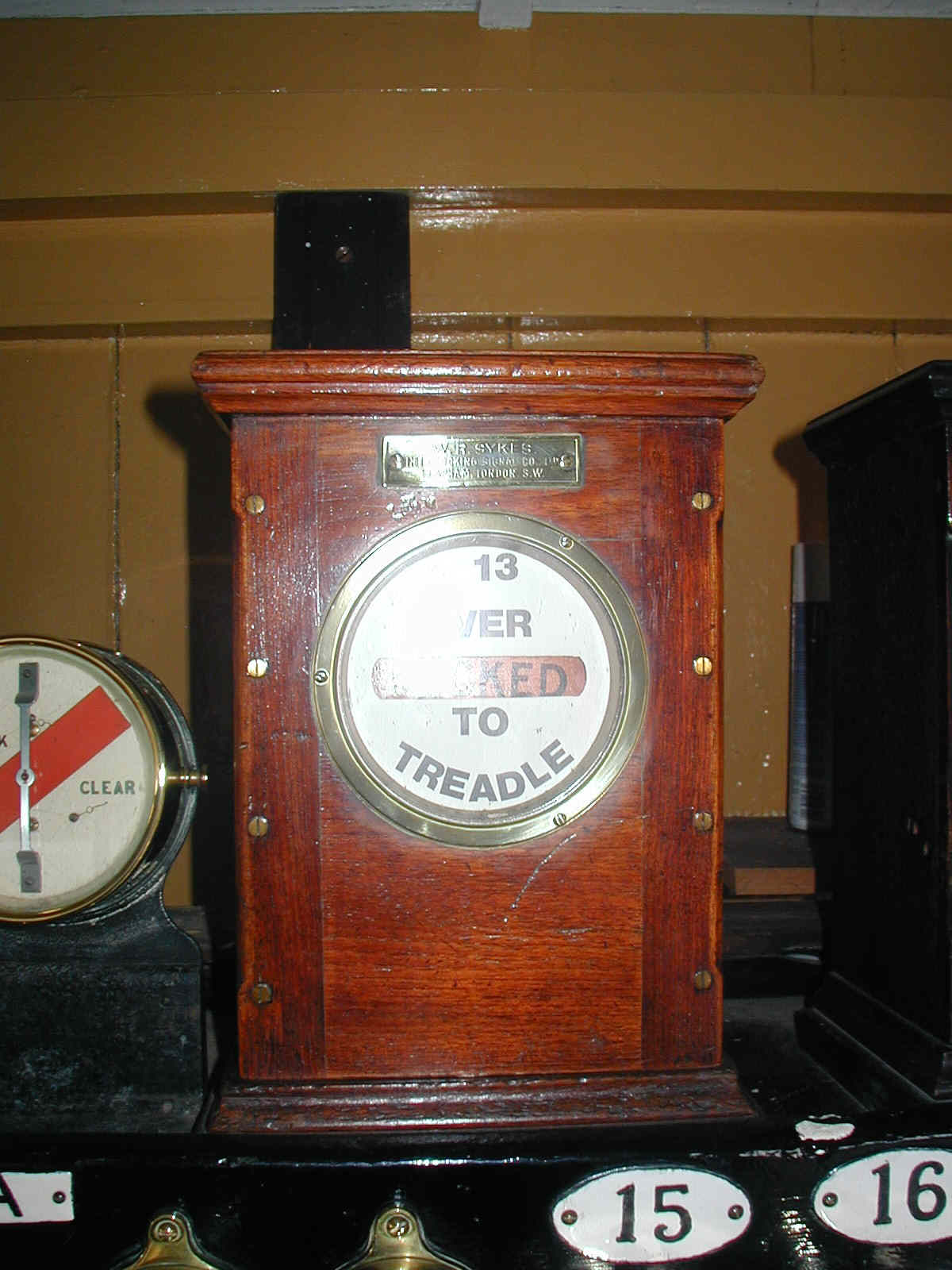
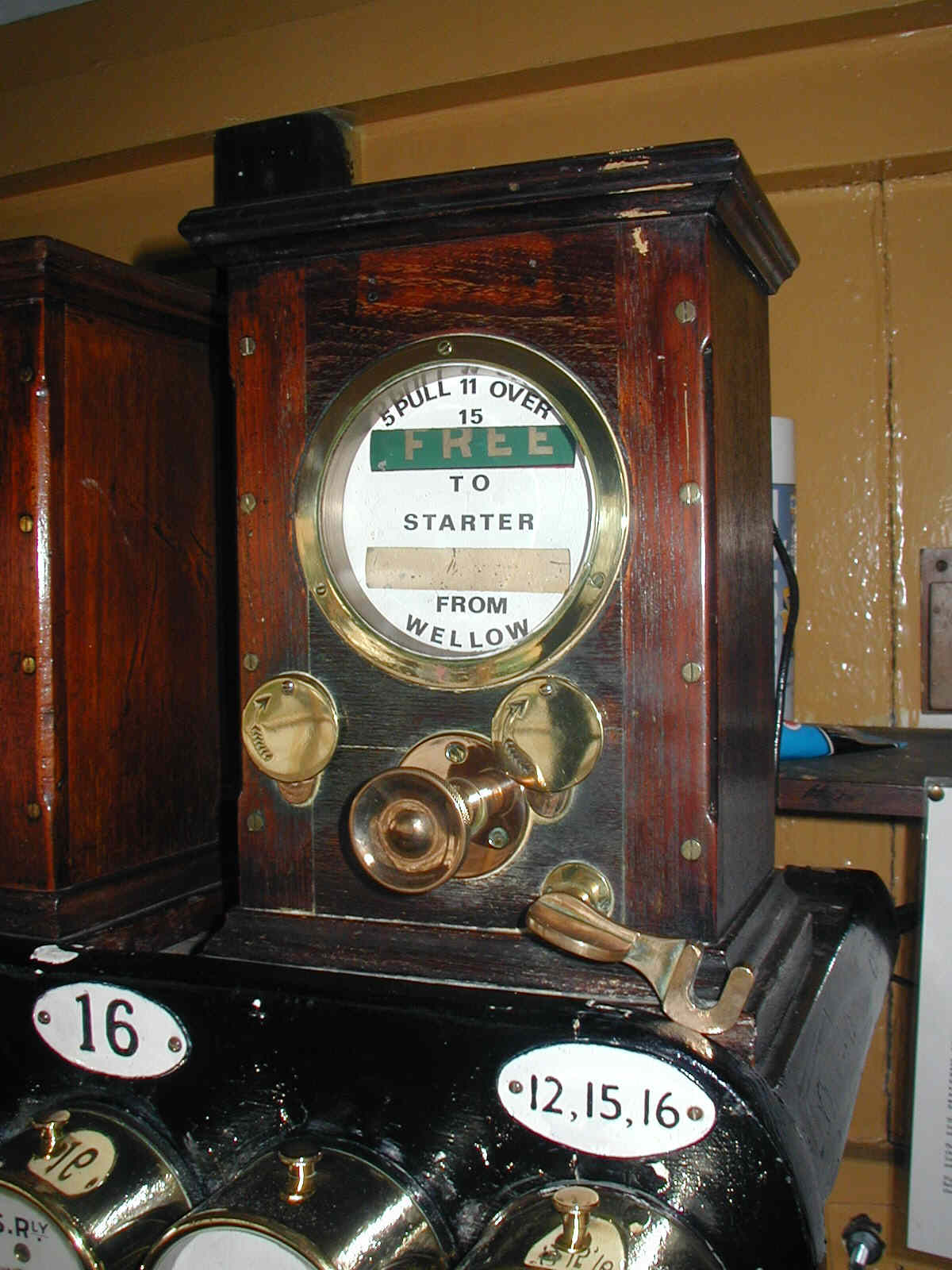
Signal 5PULL provided for movements from the single-line back onto the Up Line. Such 'wrong line' moves added to the complications of the block working to Wellow, as obviously they could not be made if an Up train had been accepted already from Wellow. To control this possible conflict, in addition to the normal three-position 'block telegraph' instrument for the section to Wellow, a Sykes 'plunger lock' instrument was provided at Midford and this was fitted with a Sykes 'point & plunger' (P&P) lock. In order to give "Line Clear" to Wellow it was necessary first for the signalman at Midford to place (or maintain) the P&P lock handle in the right-hand position and then plunge on the Sykes instrument to release an electric lock on the pegging handle of the three-position block telegraph instrument. (The operation of the plunger also released the electric lock on the lever (6) in Wellow signal-box for its Up Advanced Starting signal.) The Sykes instrument was locked then until 15 (or 12) and 13 had been pulled and replaced, thereby proving that the Up train had arrived from Wellow, passed through Midford and was on its way to Bath Junction.
When the P&P lock handle was in the right-hand position it locked levers 5PULL and 11 to ensure that - once an Up train had been accepted from Wellow - no shunting movements or use of the Up Siding points could foul the 'clearing point' in advance of the Up Outer Home (15). In order to use signal 5PULL or pull lever 11 to unlock GF 'B' then - provided that the Sykes plunger lock instrument was in its normal state - the signalman had to move the P&P lock handle to the left-hand position, thereby locking the plunger in the Sykes instrument so that it could not be used to accept an Up train from Wellow. If 5PULL was used then the Sykes plunger remained locked until lever 5 been put back to its normal mid-way position and lever 13 (the Up Starting) had been pulled and then replaced, thereby proving that the train which had been shunted back onto the Up line had now gone forward again beyond the 'clearing point' for acceptance of an Up train from Wellow.
[Note: despite the use of similar-looking Sykes instruments, this was not a example of Sykes 'Lock & Block' block working. It is probable, but not proven, that the Sykes equipment was provided at the same time as the addition of signal 5PULL.]
A number of treadles were provided at Midford in connection with the block and signal interlocking. There was also a treadle 'E' provided on the Up line a short distance in the rear of the Up Outer Home (15), which sounded a warning buzzer in the signal-box and operated a 'Train Waiting' indicator on the instrument shelf until such time as the signalman cleared signal 15 or 12. About 1923 a track circuit 'A' was installed on the Down line stretching south for 1000 yards from close to ground signal 5PUSH. This track circuit extended sufficiently far beyond the Down Advanced Starting (4) to enable the signalman, who could not see far beyond that signal because of the curvature of the cutting, to know when the tail end of a Down train had cleared the end of a stretch of 1-in-60 uphill gradient.
On 4-April-1933 (S&DJR Signal Instruction 331) signal 15 was fitted with a 'diamond sign'. This indicated to the driver of any train detained at that signal that he did not need to obey the section of Rule 55 which required the fireman to go to the signal-box, as the 'Train Waiting' indicator operated by treadle 'E' would warn the signalman of the presence of the train. [Curiously no diamond sign was provided on signal 4 despite the existence of track-circuit 'A'.] In March 1952 a second track circuit 'B' was installed through the facing points 8, extending from signal 3 towards signals 14 and 5PUSH, where it abutted to track circuit 'A'. It was probably at the same time that the 'Last Vehicle' treadle 'B' was removed.
 The 1892 signal-box at Midford was originally a conventional S&DJR TYPE 2 style,
constructed of stone with a timber superstructure decorated with a distinctive style of wavy
valencing, but it was altered rather dramatically as the result of an accident
which occurred on 29-July-1936. Described in detail in "Red for Danger"
[1], it
was rather humourous overall although obviously it could have had more serious consequences.
A locomotive shunting at Writhlington (north of Radstock) was allowed inadvertently to run
away crew-less on the Up line, propelling eight empty wagons. On reaching Midford the leading
wagon became derailed on points 8, which were still bolted for the Down line. At
10:06am (by the signal-box clock) this truck
smashed into the base of
the signal-box, knocking a large hole in the wall and shifting the lever-frame, before
ending up on the platform. As a result of this accident the box was rebuilt with a flat roof,
giving it a distinctive look, though exactly why it was given a flat roof is uncertain.
Contemporary reports mention the dispatch of a temporary box from London; nothing is
known about this, but one possibility could be that in fact a replacement 'top' was sent pending a
proper rebuild which never occurred.
The 1892 signal-box at Midford was originally a conventional S&DJR TYPE 2 style,
constructed of stone with a timber superstructure decorated with a distinctive style of wavy
valencing, but it was altered rather dramatically as the result of an accident
which occurred on 29-July-1936. Described in detail in "Red for Danger"
[1], it
was rather humourous overall although obviously it could have had more serious consequences.
A locomotive shunting at Writhlington (north of Radstock) was allowed inadvertently to run
away crew-less on the Up line, propelling eight empty wagons. On reaching Midford the leading
wagon became derailed on points 8, which were still bolted for the Down line. At
10:06am (by the signal-box clock) this truck
smashed into the base of
the signal-box, knocking a large hole in the wall and shifting the lever-frame, before
ending up on the platform. As a result of this accident the box was rebuilt with a flat roof,
giving it a distinctive look, though exactly why it was given a flat roof is uncertain.
Contemporary reports mention the dispatch of a temporary box from London; nothing is
known about this, but one possibility could be that in fact a replacement 'top' was sent pending a
proper rebuild which never occurred.
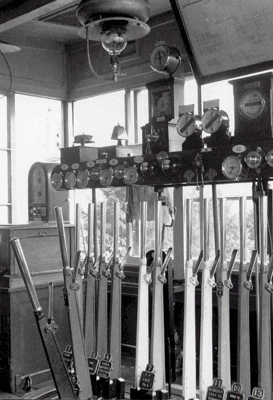
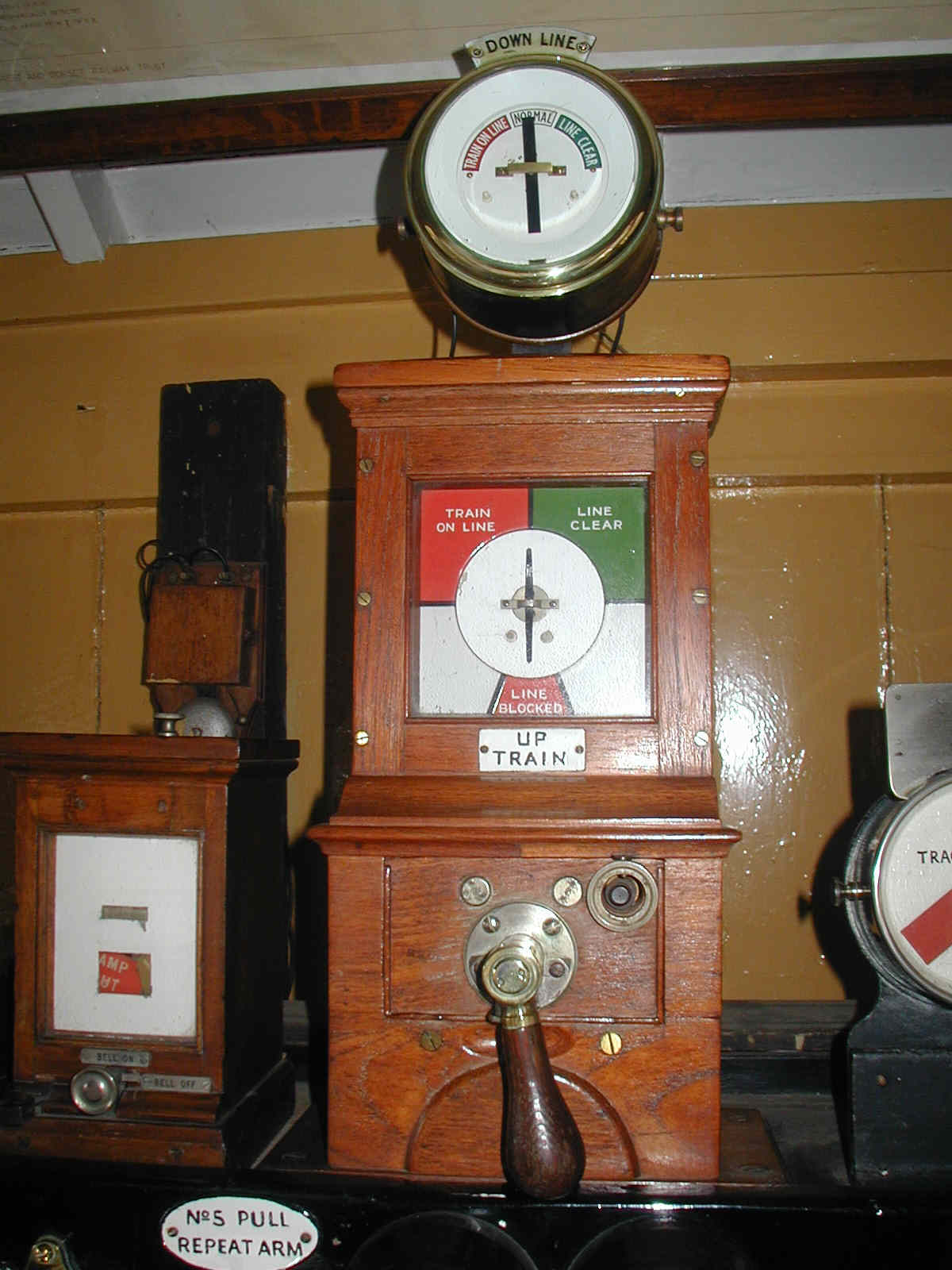
Inside the signal box in BR days (see picture) there was a variety of equipment, although a general L&SWR/SR air prevailed. The lever-frame was a Stevens 4.1/8" pattern, still with its distinctive style of rectangular brass description plates, while the instrument shelf bore a fine array of SR brass repeaters. The Tyers No 6 ETT instrument can be seen in the far corner and the S&DJR 'block telegraph' instrument on the shelf (to the left of the signal-box diagram) with the addition of an SR-pattern upper indicator. To its left is a GWR-style 'tapper' block bell (to Wellow) and to its right a pair of circular brass repeaters for the track circuits and one of the two Sykes Instruments. Click here for a more detailed explanation of the equipment shown in this 1957 picture. The signal-box was closed with the line on 6-March-1966.
Postscript...
In the years after closure almost everything was demolished at the station site and very little remains now except the platform and the viaduct. In the former goods yard the concrete base for the yard crane still exists and currently (2021) it is still just possible to see the location once occupied by GF 'A', but the site of GF 'B' has disappeared and the former Up Siding area has been buried under rubble. A rummage in the undergrowth in various locations will reveal the remaining stumps of some of the old signal posts. In recent years the New Somerset & Dorset Railway group have purchased the station site, the platform area has been cleared and some information display boards have been erected. A public footpath and cycle-track now exist on the former track-bed.
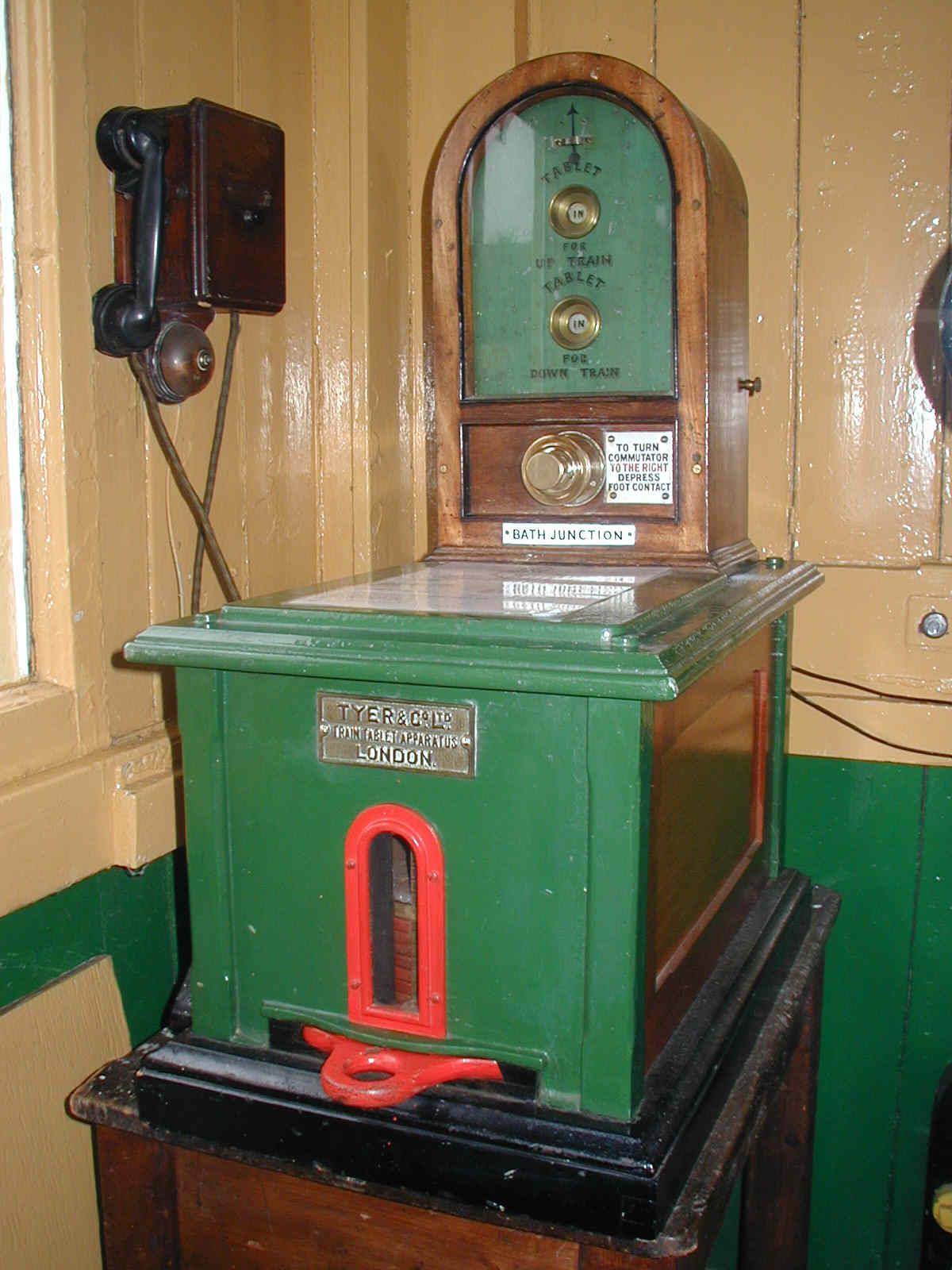
In the 1980s the Somerset & Dorset Railway Trust recreated (within the limitations of available space and equipment) a representation of the interior of Midford signal-box at their Museum at Washford station on the West Somerset Railway. Sadly the Trust had to vacate the station in 2021, at which time the display was dismantled and the equipment put into storage, but the thumbnails below provide links to a series of colour pictures showing various parts of that display. Although the display did contain a few small items of S&DJR origin, most of the equipment consisted of items of the appropriate type obtained from a variety of other sources.
| Click thumbnails for larger images | ||||||||
 |
 |
 |
 |
 |
||||
| Tyers No 6 Tablet Instrument |
S&DJR Block Telegraph Instrument |
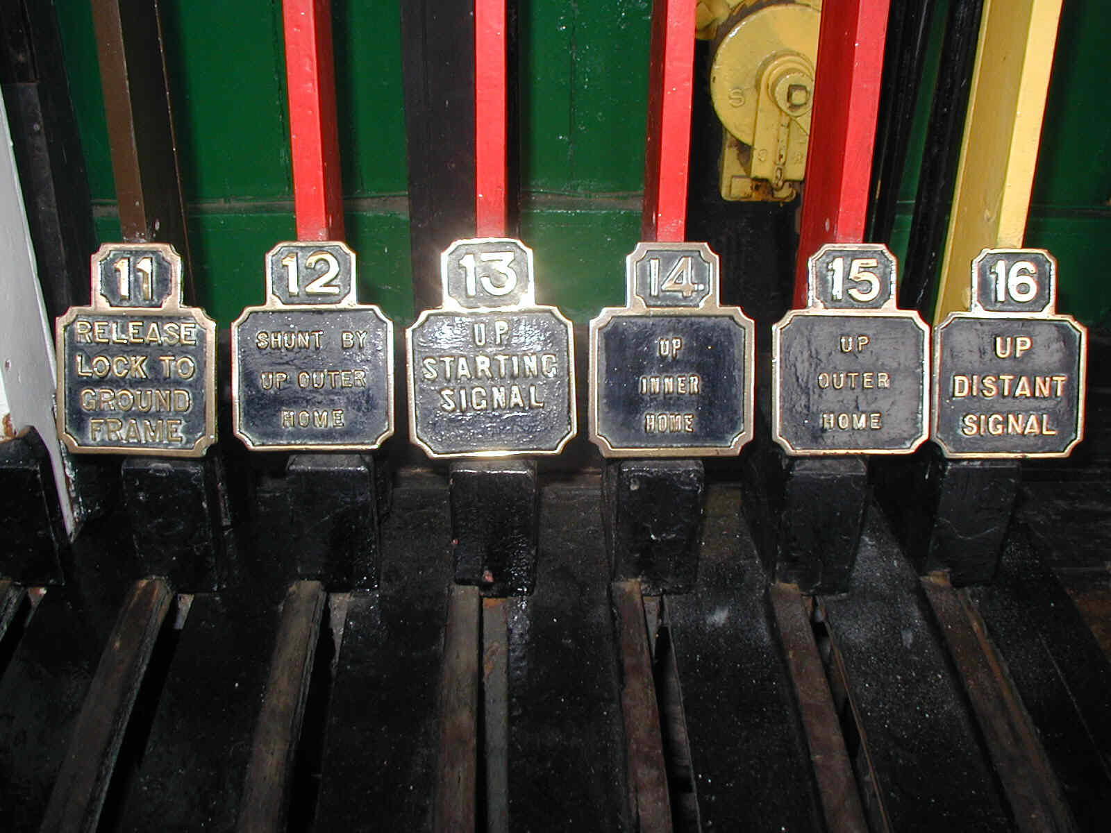
Part of the lever-frame | Indicator Lock Sykes Instrument |
Plunger Lock Sykes Instrument |
||||
© Chris Osment 2007-21
Thanks to Steve Ehrlicher and Peter Kay for material from
The National Archives, to Mike Arlett for personal reminiscences and additional archive
material, also the late Harry Wiltshire and Ivo Peters.
Midford signal-box exterior and interior photographs © Ian Scrimgeour
courtesy Signalling Record
Society.
References
|
|
|||||||
| © West Country Railway Archives 2007 Page last updated: 23 January 2023 |
URL: http://www.railwest.org.uk E-Mail: railwest@bigfoot.com |
||||||