Coupling, Handing and UNDMs
A question in the uk.transport.london newsgroup
about the use of NDMs (Non Driving Motor cars) and shunting control cabinets instead of
driving cabs set off a whole series of messages asking various questions about London
Underground train formations and types of cars. This article tries to answer those
questions and it also covers a lot of details about London Underground train operating
practices.
Contents
Background - The Central London Railway - The Wood Lane Loop - Control
Trailers - Pairing and Lettering - LER Tube Lines - Main and Train
Lines - Developments In the 1920s - Numbering - Loops and Triangles -
Uncoupling in Service - Four
plus Three - Sub Surface Trains - Metropolitan Complications - District Formations - The
District in the 1920s - The F Stock - District Uncoupling - Unit Stock
- UNDMs - Uncoupling - 8-car trains with 4 cabs - Single-ended units and double-ended units - 1972 Tube Stock - Universal
Couplers - The C Stock - 1973
Tube Stock and D Stock - The 1990s - Automatic Couplers - Coupler
Controls - Manual Control
London Underground has been running electric multiple unit
trains since 1901 and was the first operator of such trains in the UK. Since that
time, a unique range of train formations and coupling strategies have been tried,
developed and improved. The reasons for the choices made and the development of the
strategies are covered in this article, which describes the progress of the Underground's
train formation policy over a 100 years of operation.
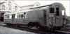
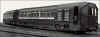 The first line in London to be provided with multiple
unit trains was the Central Line (then called the Central London Railway) in 1903,
following some experiments in 1901. Trains were formed of a set of four or five
carriages with a powered carriage at each end. This photo shows a motor car with a
trailer at the leading end of a train. The first line in London to be provided with multiple
unit trains was the Central Line (then called the Central London Railway) in 1903,
following some experiments in 1901. Trains were formed of a set of four or five
carriages with a powered carriage at each end. This photo shows a motor car with a
trailer at the leading end of a train.
Click on the image for the full size view and detailed
description.
Following American practice the carriages became known as
cars and the powered ones at the ends, motor cars. Intermediate, non-powered cars
were called trailer cars or "trailers".
Central London trains were restricted for space because of
the diameter of the tube tunnels through which they ran. The car floors were about 1
foot (300 mm) lower than those of conventional railway carriages, so the clearance between
the floor and the track was rather tight. The clearance was further reduced by the
location of the current rail in the centre of the track. These restrictions led to
a special design for the couplings between the cars. The standard UK screw coupling
would have fouled the central current rail used on the Central London so the coupling was
a simple link and pin arrangement. A central, sprung buffer plate was provided
instead of the traditional British side buffers. The hoses used to connect the
brake pipe and main reservoirs were also arranged differently so that, instead of being
hung under the headstock, they were hung from standpipes at car waist level.
Hanging the hoses at waist level produced another
problem. The cars ran in tube tunnels where the only means of escape from a stalled
train was through the ends of the train. Therefore, there had to be a walkway
through all cars to allow everyone to get out. Between cars, the gangway had to be
kept free of couplings and hoses of course, so the brake hose was placed on one side of
the gangway and the main reservoir hose on the other.
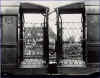 With the space on either side of the gangway occupied by
hoses, the multi-core control cable and the lighting supply cable had to be hung at roof
level, as shown in this photo of a pair of LER gate stock cars coupled. With the space on either side of the gangway occupied by
hoses, the multi-core control cable and the lighting supply cable had to be hung at roof
level, as shown in this photo of a pair of LER gate stock cars coupled.
Click on the image for the full size view and
description.
The cables usually got in the way of the head of the gateman
employed to stand on the end platforms to open and close the gates, so straps were used to
tie them up tightly. This sometimes caused the coupler heads to pull out of the
sockets as the cars went round sharp curves. It was a problem which lasted as long
as gate stock was in use on the Underground, up to 1930.
To the Top of this Page
Until 1908, Central London trains ran between Shepherds Bush
and Bank. At each end of the line, trains were reversed when the driver changed ends
and drove off in the opposite direction. The simple CLR shuttle service meant that
the train's brake pipe was always on the south side of the train and the main reservoir
pipe on the north side. In fact, the driver's position always stayed on one side
too, the north side, regardless of which direction he was driving, because the driving
cabs were built for left hand drive when going eastbound and right hand side driving when
going westbound. This was a legacy from the days of locomotive operation when the
driver’s position was on the north side of the locomotive. Signal sighting was
originally designed for this position of driving.
In 1908, the Central London was extended from Shepherds Bush
to Wood Lane and a terminal loop was built. As a result, at the west end of the
line, the trains ran from Shepherds Bush to Wood Lane and back to Shepherds Bush without
the driver changing ends. This meant that the whole train was turned round and the
cab which had faced west, now faced east. At the other end of the line (Bank) the
driver changed ends to reverse the train in the usual way. For more information
about the loop at Wood Lane, click here.
As a result of this new method of operation, a complication
was introduced into depot operations. Trains could arrive back in the depot (at Wood
Lane) either way round. If a car was removed from a train for maintenance or repair,
it had to be replaced by another car which was facing the same way round, otherwise the
hoses wouldn’t couple. Sometimes, a suitable car wasn’t available and,
rather than cancel a train, short trains occasionally appeared in service. The depot
management soon found this to be a recurring problem and they built a turntable in the
yard late in 1908 to turn individual cars when necessary.
To the Top of this Page
1908 was a busy year on the Central London because, apart
from the Wood Lane extension, they started that year to introduce short trains into
service during off-peak periods. This was partly a response to the car shortage
mentioned above and partly a mileage and energy saving exercise. As the trains were
usually of 6-cars in a fixed DM - T - T - T - T - DM formation, running shorter trains
required either a train to be taken into the depot for intermediate trailer cars removed
or for additional driving positions to be provided on the middle pair of trailers. The
latter was the sensible solution, especially since it saved a lot of complicated depot
manoeuvres and there was a bonus in that a 3-car set with one motor car had the same
performance as a 6-car set with two.
So, additional driving cabs were provided on the trailers in
the middle of a number of trains (but not all) and the train formation became DM - T - CT
+ CT - T - DM on these trains. The + indicates the normal uncoupling point.
The CT was the designation for a trailer car which had been provided with a driving
cab. It was called a Control Trailer. Some railways, which had similar
vehicles (including the Metropolitan Railway), referred to these cars as Driving Trailers.
Curiously, in view of the arrangements of the motor car driving positions, the
Central London control trailers all had the driving position on the left hand side. Trains
could therefore have left hand or right hand driving, depending on whether you were
driving from the DM car end or the CT end and which way round the train was facing.
No, Tubeprune, hasn’t tried to work out the possible variations. However, all
the variations were limited by the need to ensure that each pair of 3-car units which had
to couple together in the afternoon for the evening peak were facing in the same
direction. This was ensured by timetabling them to run one following the other after
uncoupling through the off-peak service and then re-coupling the same pair for the peak
service. Trains which didn't uncouple were stabled during the off-peak period.
To the Top of this Page
When multiple unit traction was introduced on the Central
London, it adopted a means of identifying trains by "set" numbers. The
"set" was allocated a number corresponding to the road where the train was
stabled in the depot. An identification letter was added to each motor car in the
set, "A" or "B", apparently as a way of denoting that the original
four powered axles of the locomotives had now been split into two sets of two at either
end of the train (see photo). The two
motor cars of train No 7 (normally stabled on 7 road at Wood Lane) were therefore lettered
7A and 7B. When control trailers were introduced, they were given the same letter as
the motor car with which they would run when operating as a 3-car unit
In a complete train, the lettering would look like this,
reading from west to east: ‘B’ DM - T - ‘B’ CT + ‘A’
CT - T - ‘A’ DM, see Fig. 3 below. Half the train was the “A”
half and the other was the “B” half. Put another way, there was an
“A” unit and a “B” unit. Either unit could run as a 3-car
train. When being driven from the Control Trailer end, power was provided by the
motor car at the rear.
 Typical train formations of gate stock used on tube lines. Typical train formations of gate stock used on tube lines.
Click on the image for the full size view and
description.
The Central London formation was unique in the way a 3-car
unit had the same letters at each end. The orientation was also unique in that
"A" units normally faced east and "B" units faced west. The
Bakerloo and Hampstead formations were similar to the Piccadilly but orientated north to
south. The same 6-car formation was used for Standard Tube Stock until the
introduction of 7-car trains in the late 1920s.
To the Top of this Page
The other tube lines, the Bakerloo, Piccadilly and Hampstead
Lines (the Hampstead was the Charing Cross, Euston and Hampstead railway, to give it its
full title, eventually became part of the Northern Line) which were collectively known as
the London Electric Railway (LER), all had basically similar arrangements to the Central
London. They used gate stock, which was similar in design to the Central
London’s, except bodies were of steel instead of wood and that control trailers were
provided from the outset, not converted from trailer cars.
Services over the three LER lines were introduced between
1905 and 1907. This was boom time for tube railways in London. LER trains were
equipped with the brake pipe along the north side (taking the east-west running Piccadilly
Line as the base) and the main reservoir pipe along the south side. Control and
lighting cables were hung at roof level. Automatic mechanical couplers, designed by
two Americans named Stearn and Ward in Chicago in 1902 for the North Western Elevated
Railway, were fitted between car with central, sprung buffers. Ward came to London with
Yerkes to assist with the electrification of the District. The coupler appeared on
all District and tube cars from 1905. Stearn and Ward were paid Ł1 for each one, as
it was their patent. It was only superseded by the Wedgelock automatic coupler
adopted on the 1936 Tube Stock onwards.
The Ward couplers a mechanical coupler which works
automatically when two cars are pushed together. A spring-loaded cam locks the
couplers together. To uncouple, a "coupling pole" with a hook at the end
is used to pull back the cam and allow the couplers to be separated as one car is pulled
away from the other. Hoses and jumpers had to be connected and disconnected
separately. There are still a few in use on some LUL engineers vehicles.
On the Bakerloo and Hampstead Lines, the train orientation
was originally arranged so that the brake pipe was on the east side and the main reservoir
pipe on the west side. One can imagine that the delivery arrangements had to be
very precise, since each car was delivered individually to the depot (by road in the case
of the Bakerloo and Hampstead Lines) and they each had to be the right way round to allow
them to couple to other cars.
The LER didn’t use letter identification at first but
soon adopted it when cars began to be swapped between lines from 1912. Their system
was slightly different from the Central London in that they lettered all west facing cars
“A” (i.e. cars with the driving cabs facing west, including control trailers)
and east facing cars “B”. Some lines had little enamelled plates fixed to
the cab ends showing the orientation letter. A 6-car train of LER Gate Stock was
formed like this: ‘A’ DM - T - ‘B’ CT + ‘A’ CT - T -
‘B’ DM (see diagram of Piccadilly
Line train in 1908). This arrangement did not allow units to be referred to a
“A” units or “B” units so they became know as “West end
units” or “East end units” (or north or south) as appropriate.
The LER lettering was in exact opposition to the system
adopted by the Central London, in that the "A" cars normally faced east on the
CLR instead of west as on the LER. This peculiarity persisted until the old Central
London stock was replaced in 1938-9.
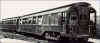 A pair of LER gate stock cars coupled. A pair of LER gate stock cars coupled.
Click on the image for the full size view
and description.
To the Top of this Page
These are American terms. The London Underground was
originally electrified using money obtained though American sources and was designed by
American engineers. Many of the LER cars were built in the US. The electric
traction technology was largely imported from the US. Much of the language used was
American and much of it has stuck to this day. That’s why the carriages are still
called cars and bogies are still called trucks on London Underground. Such
well-known phrases as “southbound” and “eastbound” are also relics of
the American heritage. Even drivers were still called motormen up to the introduction of
one person operation in the early 1980s.
As much of the technology was American in origin, many train
equipment names were American too. The brake pipe was called the train line and the
main reservoir pipe was called the main line. These names have stuck to this
day. Train lines, which are the name given to electrical cables on rolling stock in
the UK, are called control cables and the multi-core control cables between cars are
called “jumpers”.
To the Top of this Page
In the 1920s, there were significant technical developments
on the Underground. Throughout the decade, many new tube trains (the Standard Stock) and
some older ones (the Central London stock) were provided with powered sliding doors
instead of entrance gates and, towards the end of the period, electro-pneumatic brakes
were fitted to all new and many recently built cars. As a result, there were a
number of changes to the coupling arrangements.
The most significant changes for coupling were that all car
ends were enclosed and that more jumpers were needed between cars. Main line and
train line hoses remained unchanged in terms of location but jumpers were mounted on the
body ends just above the headstock, instead of at roof level. There were three
jumpers, reading from left to right when looking at an “A” end cab, Auxiliary,
Brake and Control (A, B and C). Auxiliary (originally just lighting but now
including door controls) and control jumpers were provided on all cars but the brake
jumper was added from 1929 on those cars equipped with electro-pneumatic brakes .
The jumpers were all 10-core cables with similar heads and it became important for
shunters to ensure that the right connections were made when coupling - they had to know
their “ABC”.
 1926 Standard Stock "B" end driving motor
(DM) car at Golders Green 1926 Standard Stock "B" end driving motor
(DM) car at Golders Green
Click on the image for the full size view
and description of coupling.
Another jumper was installed at roof level when emergency
lighting was introduced (about 1914) and this was retained at roof level on the new
Standard Stock trains of the 1920s. The problem was that, during uncoupling, it was
sometimes forgotten and units were parted with this jumper still connected. Damage
to them remained a problem, although many cars were modified later with the offending
jumpers moved down to waist level.
Another feature of Underground cars throughout the pre-1938
era was “side chains”. They were attached on either side of the headstock
of all vehicles to act as emergency coupling links if the Ward coupler broke. They
were supposed to be coupled at all times but often, they were left loose and sometimes
caused problems when they touched the positive current rail. They were not provided
on cars built after 1936.
 Fig 6. Front of 1929 Standard Stock "A" end
driving motor Fig 6. Front of 1929 Standard Stock "A" end
driving motor
Click on the image for the full size view
and description of coupling.
To the Top of this Page
In 1932, a car renumbering scheme was introduced across the
Underground which included a new car lettering system. The lettering scheme was
based on the use of the letters A, B, C and D to identify the four axles under a
car. Cars with the cab nearest the “A” axle became “A” cars,
those with the cab nearest the “D” axle became “D” cars. Of
course, axle lettering took account of the existing car orientation so that existing
“A” cars remained “A” cars while the “B” cars all became
“D” cars. The “B” identification plates on the cab fronts were
all changed to “D” plates. At the same time, the north side of the train
became the No 1 side and the south side the No 2 side. Diagram and more details here. The system
remains in use to this day.
All cars were renumbered. “A” cars were given
even numbers and “D” cars odd numbers. This continued the practice for
“A” and “B” cars first started on the Hampstead Line about 1914 and
gradually adopted on other lines after World War I. Cars were renumbered in
four-figure groups; 3xxx for Driving Motor cars, 5xxx for Control Trailer cars and 7xxx
for Trailer cars. The remaining 4-figure numbers were reserved for sub surface line
cars.
To the Top of this Page
The same problems experienced on the Central London following
the introduction of the loop at Wood Lane in 1908 were introduced on the Hampstead Line in
1914 with the opening of a loop at the new Charing Cross terminus. All the
Hampstead stock now became turned on every trip. The Central London train make up
problems were repeated on the Hampstead and the same solution, the building of a
turntable, was repeated at Golders Green Depot.
The Bakerloo was a north to south running line which was
gradually extended from its northern terminus at Baker Street in 1906 to a country
terminus at Watford in 1917. In the process it became connected to the District via
connections at Willesden Junction and Kensington (Olympia). When a central rolling
stock overhaul works was opened at Acton Town in 1922, Bakerloo cars could be transferred
to and from the works via this link but they became turned in the process so that the
“A” cars faced east instead of west at Acton. To ensure all cars passed
through the works with the correct orientation, the whole Bakerloo fleet was turned
(allegedly over one weekend) using the triangle of lines available at Croxley Depot, near
Watford. This meant that, from then on, Bakerloo cars ran “wrong way
round” on their own line (“A” cars face south and “D” cars face
north), a situation which has continued to this day, even though overhauls at Acton have
ceased.
To the Top of this Page
All Underground lines adopted a policy of changing train
lengths during the traffic day. The procedure usually took place whilst the trains
were in service and normally in a station platform. Gaps in the current rails were
often provided at the coupling point to allow staff to work safely between cars whilst
coupling jumpers, side chains and hoses. As mentioned above in the description of
the Central London system, careful timetabling was needed to ensure that the correct
halves of trains uncoupled after the morning peak came together in the right place for
coupling prior to the evening peak. This became quite complicated. Some lines
introduced short trains in the early morning, lengthened them for the morning peak,
reduced them during the midday peak, lengthened them for the evening peak and reduced them
afterwards only to lengthen them a third time for the late evening “theatre”
peak. Such complex operations required tight train management discipline and rapid
recovery techniques, which were developed to a fine art in the period up to the Second
World War. Since that time however, the cost of labour, the reductions in social
discipline, changing travel patterns and the difficulties in managing regular disruptions
to services, has meant that uncoupling is no longer considered a viable option.
To the Top of this Page
During the late 1920s, increases in traffic forced some lines
to increase train lengths, the Northern and Piccadilly Lines in particular. The
original, standard 6-car train formation was increased to 7-cars by the insertion of an
additional DM car. Trains were now formed: ‘A’ DM - T - T - ‘D’
DM + ‘A’ CT - T - ‘D’ DM or ‘D’ DM - T - T - ‘A’
DM + ‘D’ CT - T - ‘A’ DM, depending on the line of use and
orientation. In addition, it became the practice after World War Two, not to allow
trains to operate in service with less than two compressors. This policy required
that all Standard Stock trains had to run with two motor cars, since these were the only
cars with compressors. Uncoupling was therefore re-arranged so that the 4-car
portion always remained in service and the 3-car was uncoupled and sent to a depot or
sidings.
 Typical train formation for 7-car Standard Stock. Typical train formation for 7-car Standard Stock.
Click on the image for the full size view
and description.
Trains were still operated in 6-car and shorter off-peak
formations and, when the Central Line extensions were opened after the Second World War,
some 8-car Standard Stock trains were operated.
To the Top of this Page
Compared with the tube lines, the coupling of sub surface
line trains (District and Metropolitan Railways) was a simple business to begin
with. On both lines, which first introduced electric services on some of their main
routes from 1905, automatic mechanical couplers with centre buffers were provided.
Side buffer pads were provided on the Metropolitan cars so that they could be pushed by a
steam locomotive if necessary in emergency.
The District used the Ward coupler while the Metropolitan,
after an initial flirt with link and pin couplings, adopted the Buckeye coupler. Hoses
were coupled below the coupler (there was plenty of room under these cars) and jumpers
were duplicated on either side of the headstock, so it didn’t matter which way round
cars were coupled.
To the Top of this Page
The Metropolitan’s basic electric train formation was
6-cars comprising: DM - T - DT + DT - T - DM. The DT was a driving trailer, the same
sort of vehicle as the Control Trailer used on the tube lines. However, the Metropolitan
soon introduced complications to its electric stock fleet by using two different equipment
suppliers - Westinghouse and BTH (British Thompson-Houston) - which used different control
jumpers. In order that trailer cars could run with motor cars fitted with either
equipment, many were fitted with one firm’s jumpers on one side and the other’s
on the other side. Some of the earliest electric vehicles had Westinghouse jumpers
on both sides. From 1925, cars got turned on the triangle between Watford,
Rickmansworth and Moor Park and things became so complicated that special letter codes
were added to car ends to help shunters when they were making up trains.
Tubeprune doesn't know what these code were. Does anyone out there know?
Please contact Tubeprune if you can help.
A further complication was introduced on the Metropolitan
when they introduced, from 1908, mixed trains of saloon-bodied motor cars and compartment
stock trailers and sets of steam stock converted to electric operation. Over the
years up to the take-over of the Metropolitan by London Transport in 1934, an increasing
variety of train types and coupling variations appeared, too numerous to mention
here.
To the Top of this Page
The District started electric operations with a 7-car
standard train comprising: DM - T - T - MM - T - T - DM. The DM was a driving motor
(some of which were equipped with luggage compartments) with a driver's cab at one end,
while the MM was a driving motor (Middle Motor) with a driving cab at both ends -
otherwise referred to as a double-ended motor car. The double-ended cars were used on the
branch line services to South Acton, Hounslow, South Harrow and Uxbridge and, sometimes,
down to Putney Bridge.
From 1908, some trains were arranged to split in service at
Acton Town so that four cars went on to Ealing and three to South Harrow or Uxbridge. To
allow the 3-car portion to operate as a train, some trailers were converted to Control
Trailers. From 1910 there was a gradual increase in the District fleet which allowed the
standard train formation to be increased to 8-cars. Splitting trains were then divided
into 3-car and 5-car sets.
To the Top of this Page
By the end of the first world war, the original District Line
fleet had become very unreliable and some cars had been stored out of service. Much
of the trouble was due to the poor condition of the wooden bodies. There was then a
purchase of a fleet of new cars (the F Stock) which were
designed to be formed into the standard 3 + 5 formation. When the fleet arrived,
they were found to have a number of design problems including, most importantly, excessive
power requirements. In a subsequent re-evaluation of the District Line fleet, it was
decided to divide the rolling stock into three groups. These were “local”
wooden stock, old cars patched up to work lightly used branches, F Stock - the new cars
re-organised to reduce the power and increase operational flexibility and main line
“steel” stock, newer steel cars plus older wooden motor cars rebuilt as trailers
to allow further reliable service.
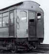
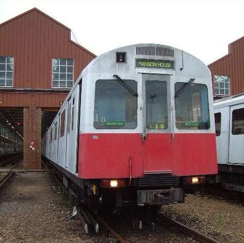
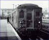 Fig 8. District Railway C Stock motor car at Olympia Fig 8. District Railway C Stock motor car at Olympia
Click on the image for the full size view and description
of coupling.
There was a lot of car rebuilding and conversion work to do
and it was the end of the 1920s before the reorganisation was complete. By then, all
three groups were operationally incompatible. The Local Stock rarely worked as more
than 2-car (DM-CT) sets, the F Stock ran in the 3+5-car formation while the Steel Stock
was reorganised into a 5+3 formation but eventually, this was developed into a 4+2+2
formation.
The 4+2+2 arrangement looked like this: ‘A’ DM - T
- T - ‘D’ DM + T - ‘D’ DM + T - ‘D’ DM. It was
developed in the late 1920s and survived until the early 1970s. It suffered from a
significant limitation in that there was no driving position at the west end of the 2-car
units so all uncoupling was limited in method and location as described later below.
 Typical train formations of District
Line stock. Typical train formations of District
Line stock.
Click on the image for the full size view
and description.
The Steel Stock had its coupling arrangements altered during
the 1920s reorganisation so that the air hoses were on either side of the end doorways
instead of under the coupler as they had been on older cars. At the west end of cars
the hoses were close to the doorway, whilst at the east end they were mounted on the
outside corners of the body. Electrical jumpers were hung below the headstock as on
earlier cars. Busline jumpers were on one side and control jumpers on the
other. Eventually, the wooden cars all disappeared and were replaced by Q Stock - a
mixture of old and new steel bodies built at various times between 1923 and 1938. These
trains survived until the early 1970s.
 Trailing end of District Railway G Stock motor car Trailing end of District Railway G Stock motor car
Click on the image for the full size view
and description of coupling.
To the Top of this Page
It is worth mentioning here that the District's F Stock was
not compatible with the main District fleet for two reasons. First the motor cars
were more powerful than other District cars and would have led to uneven acceleration in a
mixed train. Secondly, the F Stock had non-automatic acceleration, a feature which
existed on all District cars up to the F Stock's delivery but which was superseded by
automatic acceleration on the next batch of cars, the G Stock of 1923. It was not
possible to couple the two types, for obvious reasons.
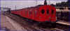 Photo of F Stock Photo of F Stock
Click on the image for the full size view and description
It was possible to couple the F Stock physically to other
cars. Photos of the first cars delivered show them coupled to older cars for test
purposes but, interestingly, the new cars are only trailers and the older cars are
providing the power.
The F Stock went to the Metropolitan after the second world
war but was retained in a block fleet - always incompatible with other stocks - and was
scrapped in the early 1960s, when it was replaced by the A Stock.
To the Top of this Page
Up to the late 1920s, District trains tended to be uncoupled
in service in 3+5 car split formations. However, from 1925, there was a gradual shift to a
4+2+2 arrangement was developed and by the Second World War, this was the usual set up.
Trains were normally run as 4- or 6-cars in the off peak and 8 cars in the peak.
The 2-car portions were always located at the east end of the train, which required
a special uncoupling procedure.
Taking Ealing Broadway as an example, the 8-car train to be
uncoupled would arrive and detrain passengers. The two cars would be uncoupled from
the east end and driven to the storage sidings at the east end of the station. The
remaining six cars would then depart on their next timetable trip. To recouple, the
6-car would arrive in the terminus and detrain passengers. The whole 6-car train
would then be driven into the sidings to meet the 2-car unit parked there, where it was
recoupled and then driven back to the terminus to pick up passengers for its next working.
To the Top of this Page
In 1936 London Underground introduced a new type of tube
train which was a complete departure from anything which had gone before. Units were
formed into blocks, with cars coupled internally by bar couplers which could only be
disconnected in a workshop environment. Units were coupled together by fully
automatic “Wedgelock” couplers, operated by a push button in the driver’s
cab. All mechanical, electrical and pneumatic connections were made through this
coupler. The new stock was called 1936 Tube Stock and was the prototype for over 1100 cars
of 1938 Tube Stock.
To differentiate between the new coupling system and the old,
the new trains were referred to as "unit stock" while older trains became known
as "car stock", the latter because individual cars could be uncoupled from a
train at any time without the need to get the train over a pit in a depot.
A surface line version of the new tube stock appeared at the
same time on the Metropolitan and District Lines as the O and P Stocks. More
appeared on the District in 1947-59 as the R Stock and the tube lines got an aluminium
bodied version of the 1938 Tube Stock known as 1950 and 1962 Tube Stocks, which replaced
the Standard Stock. All LU stocks have been designed to the same basic coupling
principles ever since.
One new feature of the 1938 Tube Stock was the non driving
motor car. This was a motor car with a full set of traction equipment but no
cab. It became known as an NDM and appeared in the normal train formation thus:
DM-T-DM + DM-T-NDM-DM. Cars would be classified “A” or “D” as
appropriate. The “A” and “D” orientation prevailed as it had
done on the earlier stocks so “A” ends could still only couple to “D”
ends. The story of the variety of train formations and coupling strategies used on the
1938 Tube Stock is complicated and is not covered here. "The 1938 Tube
Stock" by Piers Connor (Capital Transport, 1989) is a good source of additional
information. However, one feature of the 1938 TS which is important to this article
is the UNDM, which is covered next.
 This diagram shows two versions of the
1938 Tube Stock train formation as used between 1938 and 1988. The lower version
with the UNDM was seen regularly from the early 1950s. The 1972 Tube Stock currently
on the Bakerloo has the same formation with the "A cars facing south and the
"D" cars facing north. This diagram shows two versions of the
1938 Tube Stock train formation as used between 1938 and 1988. The lower version
with the UNDM was seen regularly from the early 1950s. The 1972 Tube Stock currently
on the Bakerloo has the same formation with the "A cars facing south and the
"D" cars facing north.
Click on the image for the full size view and
description.
To the Top of this Page
A new type of car was introduced to the Underground in 1949
when a re-organisation of the 1938 Tube stock allowed an opportunity to develop a middle
uncoupling point without a driving cab. The Underground was suffering from capacity
problems at this time and any way of increasing passenger space was important.
Getting way of a little used cab was a way of doing this.
The new type of car was called an Uncoupling Non Driving
Motor car or UNDM. It quickly became known as an
“undum”. The UNDM was a non driving motor car with an automatic
coupler at the outer end and a shunting control panel instead of a full width, enclosed
driver’s cab. The shunting control panel allowed driving at restricted speed
for coupling purposes only. The idea was to allow units to be uncoupled and driven
into a depot but, at the same time, to provide more passenger space where the
driver’s cab would have been. The usual train formation was: DM-T-UNDM + DM-T-NDM-DM.
 1949 Tube Stock UNDM coupled to DM car plus another photo of
the interior of an UNDM car 1949 Tube Stock UNDM coupled to DM car plus another photo of
the interior of an UNDM car
Click on the image for the full size view and
description.
To the Top of this Page
Uncoupling remained a standard operating feature of the
Underground until it was eliminated on the tube lines around 1960 and on the District in
1971. The Metropolitan hung on until 1981. Now, all trains on a line stay the same length
all day. However all London Underground trains have retained the facility to be
uncoupled in or near the middle point of the train. These days this is solely for
maintenance purposes plus, it does help if there is an emergency like re-railing a train
or getting a body from under the train after a suicide.
It is worth mentioning here how uncoupling was carried out at
on the tube lines in the 1940s and 50s. The principle established in the early 1930s
that trains should not run with less than two compressors led to a train formation for
uncoupling trains of 4- + 3-cars with the 3-car unit being stabled while the 4-car set ran
in off peak service. On the Piccadilly Line, for example, the 3-car unit was
normally at the east end of the train. Uncoupling was always carried out so that the
unit could run into a depot or siding and could only take place at Northfields (with WB
trains uncoupling and EB trains coupling).
To the Top of this Page
As we have seen, a train only requires a cab at each end for
normal operation, giving a total of two cabs for any length of train. If the train
is to split during its duty, each portion to be separated will require a cab at each
end. If this is two portions, there would have to be four cabs on a full length
train. LU trains originally designed for uncoupling in passenger service had full
width drivers cabs at each end of every unit - four on a full length train. The
Metropolitan’s A Stock is a good
example. Being designed for regular uncoupling in service, it has two 4-car units in an
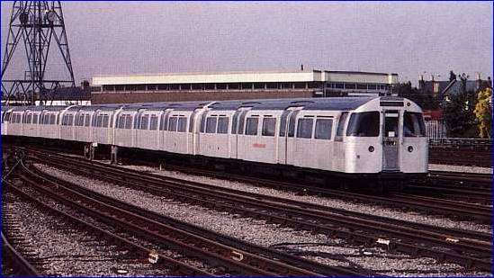
8-car train. The 1967 Tube Stock (Victoria
Line) was also designed this way, although it was never intended to uncouple the trains in
service. It did however allow 4-car trains of the stock to be tested in service on
the Central Line’s Woodford-Hainault service, where the original ATO trials were
done. The 67TS 4 + 4 formation gave a lot of flexibility when forming trains for
service in the depot. As long as a train had an operative cab at each outer end, it
didn’t matter which end of the train a unit was positioned. A defective unit
could quickly be replaced by a good one since all units were the same, with operational
cabs at both ends.
To the Top of this Page
After a few years of operation, spares became scarce on the
Victoria Line, (particularly ATO equipment) and some driving cars had equipment
“borrowed” (cab seats, destination blinds, automatic driving boxes, etc.) which
rendered them un-useable at the ends of service trains. Eventually, because of the
“robbed” cab at one end, many of the 1967 TS units became permanently restricted
to one end of a train. They then became known as south end units or north end units,
depending which end had an operative cab.
To allow some flexibility in forming trains for service, a
small block of ten units of 67TS were reserved as “double-ended units” which
could replace a “single-ended unit” at either end of a train. If you look
at the middle coupling point of a 67TS train on the Victoria Line, you will see that,
where the two middle cab fronts come together, there is no red paint on the end, unless it
is a double-ended unit. Apart from their red paint, the double-ended unit cab ends
can be identified by the ugly blisters fitted recently for mounting the inter-car safety
barriers, in case they are coupled in the middle of a train.
The A Stock is configured as 4 + 4 cars in a similar way to
the 67TS. It has to be since it needs a number of 4-car sets to operate on the East London
Line. Identification of the cabs of double-ended units is similar to the 67TS.
To the Top of this Page
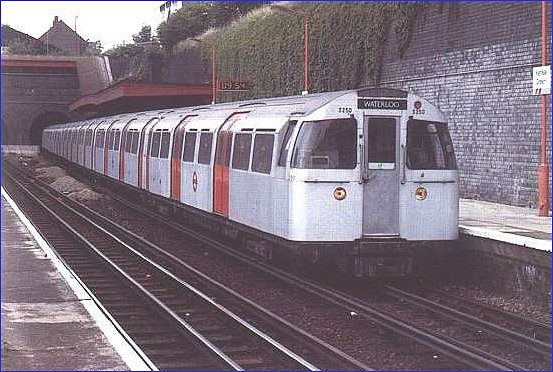
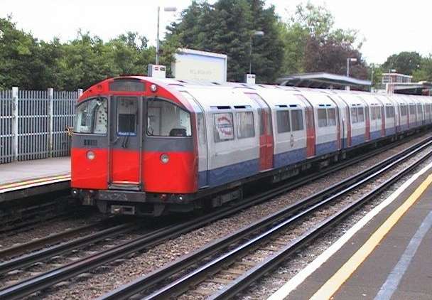
The 1972 Tube Stock operating on the Bakerloo (and which also
worked on the Northern until 3 years ago) was derived from the 67TS but it was designed to
allow trains to be formed from a 3-car unit and a 4-car unit because that’s all the
Northern Line platforms could take. The 4-car unit was given a cab at each end like
the 67TS but the 3-car only had a full cab at the outer end. The inner end had an UNDM car
with a shunting control position fitted behind a door on the left hand end wall of the car
like the 1938 Tube Stock. The shunting controls was taken from scrapped 38TS UNDMs.
Unlike the Victoria Line, the Northern Line has a loop at
Kennington. This replaced the loop at Charing Cross when the line was extended to
Morden in 1926. Quite why another loop was built after all the problems of the two
at Charing Cross and Wood Lane escapes me. I digress. The loop means that
trains get turned. For many years, the line’s operations were plagued by the
need to ensure that units faced the right way round otherwise they couldn’t be
coupled. In order to be able to couple trains both units have to face the right way
round. The 72TS on the Northern was designed so that the couplers on the UNDM could
couple to either end of the 4-car unit. As long as the UNDM was coupled to a DM car,
a 7-car train could be formed.
To the Top of this Page
The coupling arrangements for the 72TS were derived from a
development first introduced on the A Stock built in 1960-63. This stock was
designed to operate over the Metropolitan’s routes to Uxbridge, Watford and
Amersham. Trains on these routes are regularly operated over the triangle of lines
between Watford, Moor Park and Rickmansworth and therefore get turned. In order to
allow units to be coupled either way round, the electrical connections were duplicated on
either side of the coupler. This removed the need to ensure that only “A”
ends coupled to “D” ends and produced what the Underground called the
“universal” coupler. It allowed units to be coupled “A” end to
“A” end as well as “A” end to “D” end.
To the Top of this Page
This stock was introduced to replace the old COP Stock
working the Hammersmith and Circle Lines. One of the features of Circle Line
operation is that wheel wear is uneven. Although trains ran round and round the
Circle all day, they never got turned in respect of the way the wheels wore. One
side (the outside) of the wheelset always wore more than the other, so cars had to be
lifted every six months to swap the wheels from one side to the other to balance the
wear. In order to eliminate this expensive and time consuming process, universal
couplers were provided on the C Stock so that it could operate with units either way
round. To ensure that they were turned regularly, two passenger trips per day are arranged
for Circle trains to run from Tower Hill to Whitechapel, where they reverse and then go to
Hammersmith.
Another unusual feature of the C Stock is that it is designed
as a 2+2+2 train formed DM-T + DM-T + T-DM. This was because it was intended that it
would be the forerunner of a new fleet for the sub surface lines which would run as 4-, 6-
or 8-car trains on the District or Metropolitan Lines. It was not to be. In
any event, the 2-car units were provided with automatic couplers at each end.
Originally, the C Stock did not have driving facilities at
the trailing end either but they were able to be uncoupled in a depot yard. The trailers
were actually “uncoupling trailers” but they were never officially described as
such, probably because you couldn’t drive from the trailer. Without driving
facilities at the trailing end, coupling, which took place only in depots, was a cautious
affair. A man had to ride on the trailing end directing the driver who was driving
in reverse from the cab at the other end of the unit. This situation was rectified
with the refurbishment of the fleet in the early 1990s, when all trailers were fitted with
shunting controls.
To the Top of this Page
With a logical progression of the design process, the
operationally developed "single- and double-ended unit" Victoria Line train
formation was applied to the 1973 Tube Stock (73TS) built for the Piccadilly Line. Trains
were formed of single-ended 3-car units coupled back to back to form 6-car service trains.
The 3-car single-ended units were provided with UNDMs equipped with automatic couplers and
shunting control panels. A batch of 20 double-ended 3-car sets were kept for
flexibility and to allow a unit to work the (now closed) Aldwych branch.
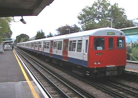
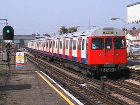
The D Stock, built from 1978-81 for the District Line, was
simply a surface line version of the 73TS. The main fleet was made up of
single-ended units and some double ended units were included to provide flexibility.
 Fig. 13 showing the 6-car formation of both 1973 Tube Stock
(Piccadilly Line) and D Stock (District Line). It is the same for both stocks. Fig. 13 showing the 6-car formation of both 1973 Tube Stock
(Piccadilly Line) and D Stock (District Line). It is the same for both stocks.
Click on the image for the full size view and description
The upper formation shows a double-ended unit in the place of
an "A" end single-ended unit, while the lower diagram shows "A"
single-ended unit coupled to a "D" single-ended unit. Note that both
ends of the double-ended unit have automatic couplers but the single-ended units have
couplers on the UNDMs only. The outer (cab) end has an emergency mechanical coupler.
On both 1972 and 1973 Tube Stocks and the D Stock, not all
cab ends are equipped with automatic couplers. Only the cab ends where train
formations require the coupler, have it. The outer ends of any unit with an UNDM do
not need it and these positions are fitted with an emergency mechanical coupler.
To the Top of this Page
Three sets of tube stocks have appeared during the 1990s -
the 1992 Tube Stock for the Central Line, the 1995 Tube Stock for the Northern and the
1996 Tube Stock for the Jubilee. Looking at the later stocks first, both 95 and 96 stocks
have the 3 + 3 formation with cabs at the outer ends and UNDMs in the middle. There are no
double-ended units. It is thought that better maintenance regimes will remove the
need to have spare flexibility. We'll see.
 Fig. 14. Diagram of 6-car
formation of 1996 Tube Stock for Jubilee Line. Fig. 14. Diagram of 6-car
formation of 1996 Tube Stock for Jubilee Line.
Click on the image for the full size view and description
The 1995 Tube Stock on the Northern Line is similar except
that the "universal" couplers allow "A" units to couple to other
"A" units and likewise with "D" units.
The only difference in their coupling arrangements is that
the 95TS on the Northern gets turned on the Kennington loop and therefore universal
couplers are used to allow “A” ends to couple to other “A” ends as
well as “D” ends. The 96TS doesn’t get turned and is
“handed” so only “A” ends will couple to “D” ends.
Curiously, both stocks are equipped with automatic couplers at the cabs ends. There
seems to be little logic in this, since the ends cannot be coupled to anything for normal
service use and, if emergency coupling is needed, electrical connections are notoriously
unreliable under failure conditions and may end up transmitting the fault from the
defective train to the assisting train.
The 92TS built for the Central Line is based on a
2+2+2+2+2-car formation. The 2-car unit is self-contained with cabs provided at one
end of some units, while the rest have no cabs. Each end of every unit has a fully
automatic universal coupler, necessary because the stock gets turned regularly on the
Hainault loop. As there are more units with cabs, it is possible to see trains formed with
cabs at coupling points but this is rare.
To the Top of this Page
Fig 15. Diagram of current design of LUL
auto-coupler, showing main parts.
The automatic coupler used by London Underground is basically
the same design which first appeared in 1936. The mechanical portion consists of a cast
steel coupler head with a tongue and throat which mate with the tongue and throat of the
other coupler. Once the tongues are in the throats, they are locked into place with wedges
driven by air pressure operated pistons.
When the two couplers come together, the air connections
between the units are completed by matching holes lining up. Rubber washers prevent air
escaping at the joint. Electrical connections are housed in two terminal blocks mounted on
either side of the coupler head. The connections are made through spring loaded butt
contacts provided for each circuit. A universal coupler can have up to 64 electrical
connections across the coupler faces.
In order to protect the electrical contacts while the units
are uncoupled, the contact blocks are covered automatically as the two coupler heads part.
The covers are curved so that they swing over the face as the uncoupling takes place. They
are referred to by LU as "Dutch ovens". There is a lug at the base of each
contact block which pushes the "oven door" open as the two couplers meet. The
doors are spring loaded so they will close automatically as the units part.
 Fig 16. Universal automatic coupler on A Stock
driving motor car. Fig 16. Universal automatic coupler on A Stock
driving motor car.
Click on the image for the full size view
and description of coupling.
To the Top of this Page
The original design of auto coupler had automatic controls.
The driver wanting to uncouple two units would release the parking brakes of the unit he
was to operate from, enter the cab of that unit at the coupling point, "open up"
the controls to release the brakes and push the "Uncouple" button in the cab.
As the uncouple button was pushed, an electro-pneumatic
"coupler valve" on each unit operated a "coupler engine", a
pneumatically driven camshaft which drove the valves controlling the couplers. Each
coupling engine went through a process of releasing the wedges securing the coupler
tongues, isolating the main and train line connections from the coupler face and resetting
the tripcock, which was isolated while the units were coupled. These operations were
achieved through a series of five cam-operated valves on the camshaft.
As the coupler wedges released the tongues, the spring buffer
provided between the units pushed the operating unit away from the static one and the two
units were automatically uncoupled. Of course, the whole system depended on the two e-p
valves operating at the same moment and on both coupling engines turning together to
release the wedges. The difficulty of achieving this on couplers which had not been used
for a long period often led to failures. If this occurred on a service train due to
uncouple after the morning peak, the train would remain coupled until it could be changed
over (if enough spares were available) or until the evening peak.
Coupling was a simpler operation. One unit was driven up to
the other so that the two couplers engaged and a "couple" button was pressed to
turn the coupling engines. The coupling engines operated the valves to complete the main
and train line connections, lock the wedges into place and isolate the tripcocks.
Coupler failures, usually during uncoupling led to some
bizarre procedures to get units to uncouple. The first step usually involved a man in each
car, manually lifting the uncouple valves on the count of "one, two, three". If
this didn’t work, the air was manually bled off the units and a pin and long lever
was used to manually push back the wedges through a slot in the top of the coupler head.
If this still didn’t work, the air connections to the couple and uncouple valves were
reversed and air re-applied to the train.
To the Top of this Page
Frustration with the push button control led to a new design
for the 1967 Tube Stock built for the Victoria Line. The coupling process was redesigned
to allow manual operation on each unit sequentially instead of requiring parallel and
instantaneous operation. The coupling engine was moved from its former remote position
under the offside cab floor to a cabinet inside the
driver’s cab.
The camshaft is mounted vertically and has three operating
positions, "Coupled", "Wedges Back" and "Uncoupled". When a
train is to be uncoupled, the control is moved to "Wedges Back" in both cabs,
the units are driven apart and then the control moved to "Uncoupled". Although
it takes longer than the push button control, this is a more reliable system and time is
not a crucial as before since uncoupling no longer takes place in service.
|


